


975-0697-01-01 9
Planning Preparations
This guide for use by qualified personnel only.
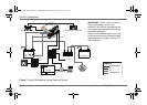
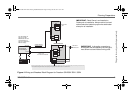
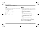
Figure 4 Wiring and Breakers Block Diagram for Freedom SW 230V 2524 / 3524
2524 and 3524
Inverter/Charger
230 V AC OUT
230 V AC IN
Battery (Bank)
24 V
HOT = BROWN, BLACK, OR GREY
NEUTRAL = BLUE
GND = GREEN WITH YELLOW STRIPE
HOT BUS
TO AC APPLIANCE
LOADS
INVERTER AC SUB PANEL (TYPICAL)
MAIN ELECTRICAL PANEL
FROM SHORE OR
GENERATOR POWER
HARDWIRE CONNECTIONS
30 A MAX in pass-through
Neutral
GND
15 A
20 A
Neutral
GND
30 A
MAIN
NOTE: The DC grounding conductor may be one size smaller than the minimum size conductor required for the DC current carrying conductors providing the overcurrent protection device in the DC
positive conductor is rated no greater than 135% of the ampacity of the DC grounding conductor and the conductor is no smaller than 2mm
2
.
IMPORTANT:
Read Owner’s and Installation
Guides prior to installation. Always refer to local and
national electrical codes for proper wire and breaker
sizes prior to installation.
See “DC Cabling” on
page 13 and “DC
Disconnects and Over-
Current Devices” on
page 14 for cable sizes
and fuse ratings.
IMPORTANT:
In Australia, connection to
shore power that is supplied by the utility grid,
must follow local and national wiring rules.
Freedom SW 3K2K 230V InvChg Install Guide.book Page 9 Friday, June 20, 2014 9:11 AM