


975-0697-01-01 43
Stacking Features
This guide for use by qualified personnel only.
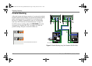
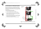
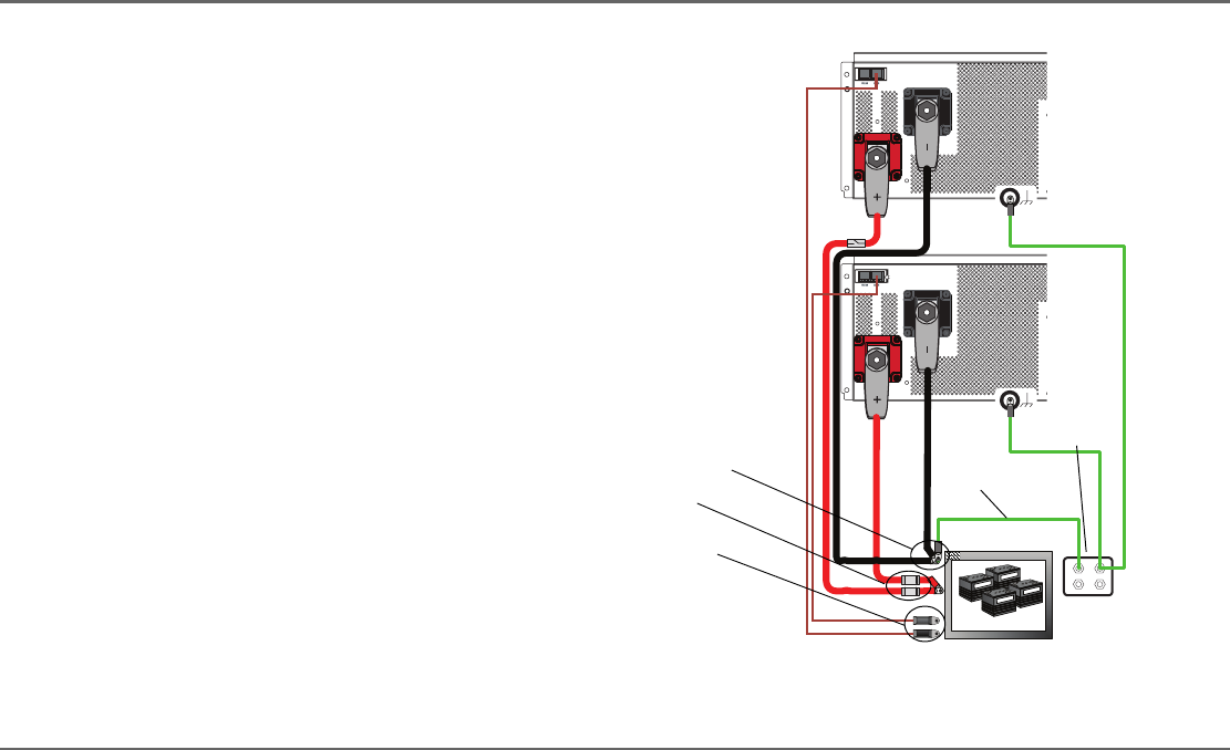
DC Connections for Stacked Inverters
Individual overcurrent devices are to be used between the battery
positive and each inverter. Keep cable lengths to the two inverter/
chargers the same in order to balance cable losses. If not, the battery
cable difference in length between the two inverter/chargers should
not exceed 30 cm.
Connect the stacked system as follows:
1. Connect each negative terminal to the battery.
2. Connect a earth (ground) wire to the common negative.
3. Connect each positive terminal of the inverter to the battery
through a DC disconnect in each positive line. Do not tie the
positives together between inverters.
4. Connect the earth (ground) bonding wire from each inverter to
the same location on the vehicle chassis. Use that same length
and gauge wire for both inverter/chargers.
5. Connect the battery temperature sensors (BTS), if needed.
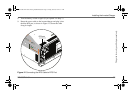
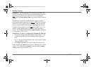
Figure 17
Connecting Battery Cables and DC Earth/Ground Wires
Battery
Negative
Battery
Positive
Battery
Negative
Battery
Positive
Earth/
Ground
1
2
3
4
5
Two Freedom SW
3524-230 units
shown.
Freedom SW 3K2K 230V InvChg Install Guide.book Page 43 Friday, June 20, 2014 9:11 AM