Fort Assembly
Phase 8
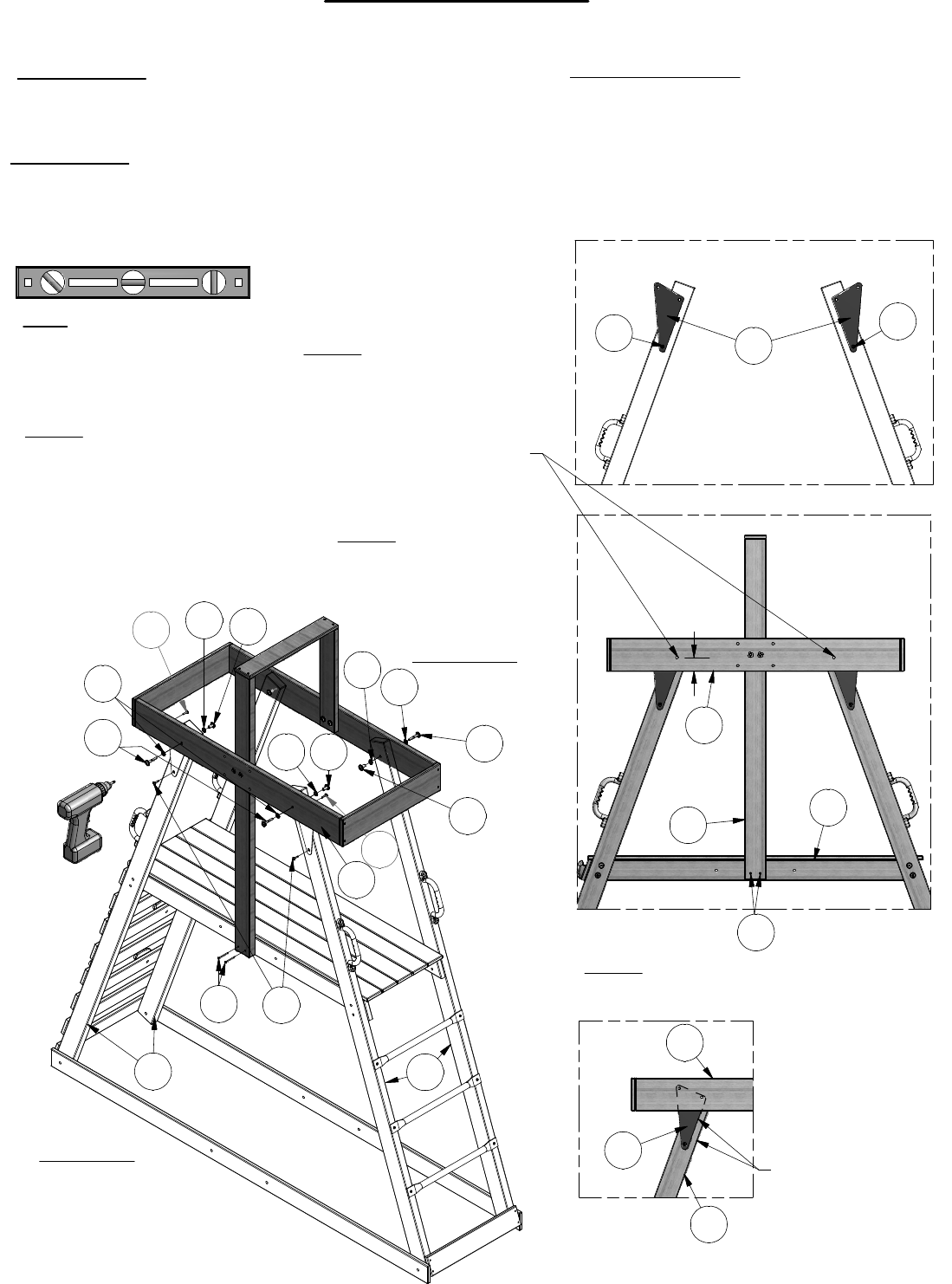
Phase Notes
• Assemble with hardware as shown.
• The Roof Assembly attaches differently on back of the
Fort then it does on the front.
G1
BV
K
AC
AD
D
BJ
BJ
GL
D
AD
GL
E2
G1
GL
BJ
BJ
BV
BJ
Parts needed:
• (2) GL - PLATE 3 HOLE BLUE - A100149
Hardware needed:
• (4) D - NUT BARREL WH 5/16x7/8 - H100005
• (4) AD - WASHER LOCK EXT 12x19 - H100031
• (4) AC - WASHER LOCK EXT 8x19 - H100030
• (4) BJ - SCREW TAPPING 14x1 - H100080
• (4) K - BOLT WH 5/16x2 - H100012
• (2) BV - SCREW PFH 8x2-1/4 - H100091
Note: It is vital that the fort
be level before and after
each phase of assembly.
E2
E1
DAD
FRONT SIDE
Step 1: Attach Roof
Assembly to front uprights
of fort using hardware 'D',
'AD','AC' and 'K', as
shown.
Step 3: Finish securing the Fort
Plate 'GL' to the uprights and
cross beam using Screws 'BJ'
through open holes, as shown.
BACK SIDE
AC
K
Step 2: Attach Roof
Assembly to back of fort
by placing Bolt 'K' and
Washer 'AC' through the
Cross Beam 'G1' and the
top hole on Plate 'GL', then
through the upright and
secure using hardware
'AD' and 'D', as shown.
Edges Parallel
Step 4: Attach 'E3' roof upright to 'H1'
floor brace using Screws 'BV', as shown.
H1
E3
These two holes not centered.
Correct installation requires the
holes to be installed as shown.
2
3
/
1
6
"


