


12 General Information
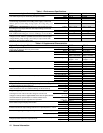
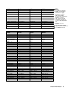
Table 1-1 Performance Specifications
Agilent Technologies Model 6010A 6011A
DC Output: Voltage, current and power spans indicate range Volts 0-200 V 0-20 V
over which output may be varied using front panel controls.
Amps 0-17 A 0-120 A
Maximum Power 1000-1200 W 840-1072 W
Load Effect (Load Regulation) Voltage load effect is given for a load
current change equal to the current rating of the supply. Current load
Voltage 0.01% + 5 mV 0.01% + 3 mV
effect is given for a load voltage change equal to the voltage rating of the
supply.
Current 0.01% + 10 mA 0.01% + 15 mA
Source Effect (Line Regulation): Given for a change within the rated
line voltage for any output within the rated output voltage, current and
Voltage 0.01% + 5 mV 0.01% + 2 mV
power of the supply Current 0.01% + 5 mA 0.01% + 25 mA
PARD (Ripple and Noise): Measured at any line voltage and under any
Voltage 22 mV/50 mV
2
8 mV/50 mV
load condition within rating (rms 10 Hz to 10 Mhz/p-p 10 Hz to 20 MHz) Current 15 mA/
1, 4
120 mA/
1,4
Load Effect Transient Recovery: Maximum time required for output
voltage to recover within the specified band around the nominal output
Time 10%/50% 2 ms/3 ms 2 ms/3 ms
voltage following a step change (10% or 50%) in output current while
operating in the constant voltage mode
Level 10%/50% 150 mV/500mV 100 mV/300mV
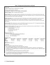
Table 1-2. Supplemental Characteristics
Agilent Technologies Model 6010A 6011A
Programming: Given for control of the
Voltage Resolution
70 mV 5 mV
output over the GP-IB or with front panel controls Current Resolution 7 mA 40 mA
Front Panel Voltmeter:
Range
20 V, 200 V 20 V, 200 V
Resolution 100 mV, 1 V 10 mV, 100 mV
Accuracy 0.65% + 3.5 counts,
0.65% + 3.5 counts
0.6% + 2 counts,
0.8% + 2 counts
T.C. (per/°C)
80 ppm + 1 mV,
80 ppm + 1 mV
80 ppm + 1mV,
100ppm + 1 mV
Front Panel Ammeter:
Range
20 A 200 A
Resolution 10 mA 100 mA
Accuracy 0.6% + 4 counts 0.7% + 300 mA
4
T.C. (per/°C)
100 ppm + 2 mA 100 ppm + 3 mA
Display OVP:
Range
2000 V 200 V
Resolution 1 V 100 mV
Accuracy 2.5% + 1.1 V 2.5% + 625 mV
T.C. (per/°C)
200 ppm + 3 mV 150 ppm + 3 mV
Maximum AC Input Current: +6% -13% (48-63) Hz
100 Vac (Opt.100)
24 24
120 Vac (Std.) 24 A 24 A
220 Vac (Opt.220) 15 A 15 A
240 Vac (Opt.240) 14 A 14 A
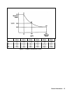
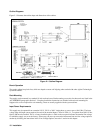
Typical input power at rated output power: (see point P
2
on Figure 1-1)
1435 W 1375 W
Temperature Coefficient: Output change per degree Celsius change
Voltage 80 ppm + 15 mV 100 ppm + 2 mV
in ambient following 30 minute warm-up. Current 100 ppm + 4 mA 180 ppm + 15 mA
Drift (Stability): Change in output (dc to 20 Hz) over 8-hour internal
Voltage 0.03 % + 17 mV 0.03% + 3 mV
under constant line, load, and ambient following 30-minute warm-up Current 0.03% + 5 mA 0.1% + 25 mA
Programming Response Time: The maximum time required
Settling
Band
300 mV 30 mV
to change from zero volts to full scale voltage or from full scale Up Full Load
300 ms (0.4Ω ) 300 ms (40 Ω)
voltage to 2 volts (6 volts for Agilent 6028A and 5 volts for Agilent 6015A) No Load 300 ms 300 ms
and settle within the specified band. Full load is defined as the Down Full Load
500 ms (0.4Ω )
600 ms
resistance equal to Vp1/Ip1. Light load is as specified Light Load
3.5 s (open Ω) 1.5 s (50 Ω)
Overvoltage Protection: Trip voltage adjustable via front
Range
0-214 V 0-22 V
panel control using the Display OVP function Resolution 600 mV 100 mV
Accuracy 0.3% + 1.25 V 0.25% + 625 mV
Voltage 0.3% + 60 mV 0.25% + 2 mV
Monitoring Output Accuracy: 0 to 5 V signals from rear panel terminals that
indicate 0 to full scale output voltage and current. Output impedance = 10K Ω.
Current
0.36% + 10 mA 0.3% + 35 mA
Remote Analog Programming Accuracy
Resistance (0 to 4K) Voltage 0.5% + 35 mV 0.5% + 215 mV
Current 1% + 800 mA
3
1% + 170 mA
Voltage (0 to 5V) Voltage 0.25% + 35 mA 0.3% + 215 mV
Current 0.4% + 800 mA
3
0.36% + 170 mA
Ac power on 17 A 50 A
Reverse Voltage Protection: Maximum continuous current caused by reverse
voltage impressed across the output terminals.
Ac power off
7 A 20 A