


Operating Instructions 41
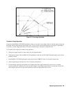
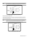
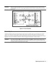
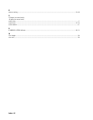
Caution: When two supplies are operated in series, they should be programmed to the same voltage to prevent
possible damage to the lower voltage supply during short circuit conditions. Contact the factory if this is
not possible.
Figure 3-13. Series Operation
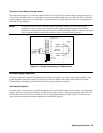
Monitor Signals
Amplified and buffered voltage and current monitor output signals are available at the rear-panel terminal strip. These
signals can be connected to remote meters to indicate output voltage and current. The signals vary from 0 to 5 volts to
indicate a zero to full-scale output. Both monitor-output terminals are referenced to the monitor-common terminal. Output
impedance of the monitor terminals is 10.2k
±
5%; a load of 1 megohm will maintain 1% reading accuracy.
Caution: The common terminal ( M) is internally connected to the minus (-) output terminal. If either power
supply output terminal is grounded the remote monitor terminals must not be grounded. Failure to float
the remote terminals may damage the power supply.
= Handle
= Handle