


20 Installation
The offset pin on the standard power cable three-prong connector is the ground connection. If a two-contact receptacle is
encountered, it must be replaced with a properly grounded three-contact receptacle in accordance with the National
Electrical Code and any local codes and ordinances. The work should be done by a qualified electrician only.
Note: To reduce noise pickup, it is good practice to keep the ac input lines separated from signal lines.
Line Voltage Option Conversion
Caution: Conversion to or from 100 V operation requires replacement of internal components and calibration in
addition to the line voltage components, and is to be done only at the factory. Failure to configure and
calibrate the power supply properly may result in damage to the unit.
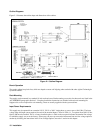
Agilent Models 6010A, 6011A, 6012B and 6015A.
Line voltage conversion is accomplished by adjusting three components: a two-section line select switch, and a line-voltage
jumper. To convert the supply from one line voltage option to another, proceed as follows:
WARNING: Some components and circuits are at ac line voltage even with the LINE switch off. To avoid
electric shock hazard, disconnect line cord and load, and wait two minutes before removing covers.
a. Remove the outside cover by removing the four screws that hold the carrying straps, spread the bottom of the cover
slightly and carefully slide the cover to the rear of the supply until it is clear. Next remove the top inside cover by
removing the nine screws, four on top, three on right side, and two on left side, which connect the top inside cover to
the supply chassis.
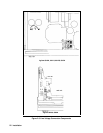
b. Remove the FET board to reach the line-voltage jumper (W1) terminals.
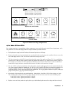
c. Use a small-blade screwdriver to set the two switch sections of S2 to match the pattern printed on the main board for
the nominal line voltage to be used. For example, to set switches for 120 V operation, move forward switch section so
that its white slot is toward front of supply and move rearward switch section so that its white slot is toward rear of the
instrument.
d. Set switch S1 to match the rearward section of S2, i.e., toward the rear for 100/120 V operation, toward the front for
220/240 V operation.
e. One end of W1 is soldered to the main board; the other end has a female quick-connect terminal that fits onto one of
two terminals soldered to the main board. For 100 V or 120 V operation, W1 must be connected to terminal J9; for 220
V or 240 V operation, W1 must be connected to terminal J10. Be certain that the jumper is firmly mated with the
connector on the main board. Do not grip jumper insulation with pliers; either grip the jumper wire by hand or grip the
jumper terminal with pliers.
f. Replace FET board, inside top cover and outside top cover. Mark the unit clearly with a tag or label indicating correct
line voltage to be used.
g. Change line label.