


Operating Instructions 31
circuits within the supply the power supply output drops to zero and the UNREGULATED indicator turns on. The power
supply can be disabled by overvoltage, overtemperature, or by low or high ac line (mains) voltage.
Overvoltage. If the voltage across the power supply output terminals rises above a preset level, possibly because of a
hardware malfunction, the overvoltage protection (OVP) circuit will trip. If this occurs, the power supply will be disabled
and the OV indicator turned on. To reset the OVP circuit, first ensure that the condition that caused the overvoltage is
corrected, then turn the power supply off and back on.
Overtemperature. If the overtemperature protection circuit trips, the power supply will be disabled and the OT indicator
turned on. The overtemperature circuit will reset automatically and the power supply output will be restored when the
temperature drops sufficiently for safe operation.
AC Line Over/Under Voltage. If the ac line (mains) input voltage increases or decreases beyond the range for safe
operation the power supply output may be disabled. The power supply output will be restored when the input voltage
returns within range.
Operating Modes
Settings or the rear panel Mode switch determines the operating mode of the unit. In Normal operating mode the unit is set
for local sensing, (where the output voltage is sensed directly at the output terminals) and front panel voltage and current
programming. Other operating modes covered in this chapter include remote voltage sensing, remote programming of
voltage and current using either external resistors or voltage sources, and multiple supply operation such as auto parallel and
auto series.
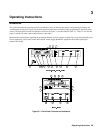
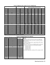
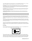
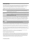
Figure 3-3 shows six switches on the rear panel that configure the power supply programming (either front-panel controls)
or remote analog programming (resistance or voltage). When shipped from the factory the switches are set for front-panel
programming, which is the normal operating mode for this power supply. The two analog programming modes are available
for use in special circumstances.
Typically, only one programming mode is used for both output parameters (voltage and current). However, the mode
switches allow voltage and current to be programmed independently. For example, voltage could be programmed from the
front panel, while current is resistance programmed. Note that only one programming mode can be used for each parameter
at one time.
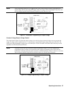
Normal Mode
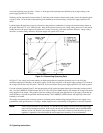
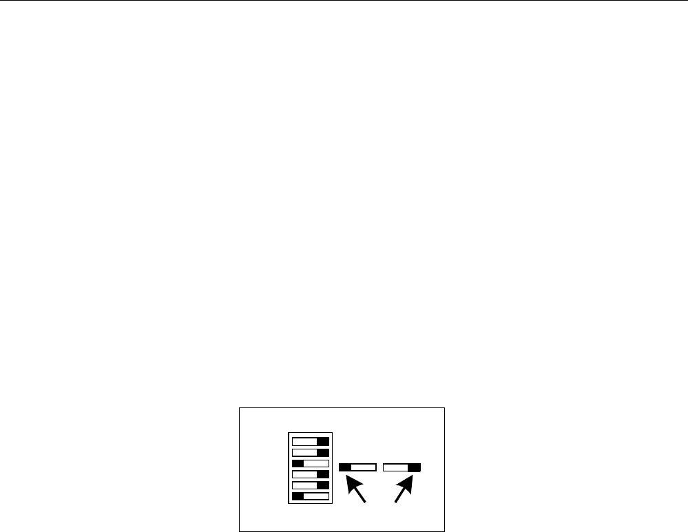
The unit is shipped from the factory configured in the normal operating mode – with the + and – outputs jumpered to the +
and sense connectors. The mode switch is set as shown in the following figure.
Figure 3-3. Factory Settings, Mode Switch
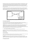
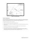
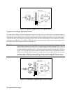
The power supply can operate as a constant voltage (CV) or constant current (CC) source over a wide range of output
voltage and current combinations. The specifications table contains a graph showing the overall output range of the power
supply. Figure 3-4 shows a rectangular operating locus that is defined by voltage and current settings of the power supply.
The load resistance determines the point on that locus at which the power supply actually operates. Three load-resistance
lines are shown on Figure 3-4. The line representing load resistance A, the highest load resistance shown on the graph,
Handle
B6
B5
B4
B3
B2
B1
01
01