


30 Operating Instructions
Either positive or negative voltages can be obtained from the supply by grounding one of the output terminals. It is best to
avoid grounding the output at any point other than the power supply output terminals to avoid noise problems caused by
common-mode current flowing through the load leads to ground. Always use two wires to connect the load to the supply
regardless of where or how the system is grounded. Never ground the system at more than one point. The maximum
potential (including output voltage) that either output terminal is from ground must not exceed that specified on the output
label on the rear chassis.
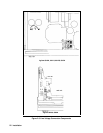
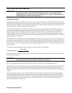
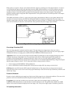
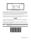
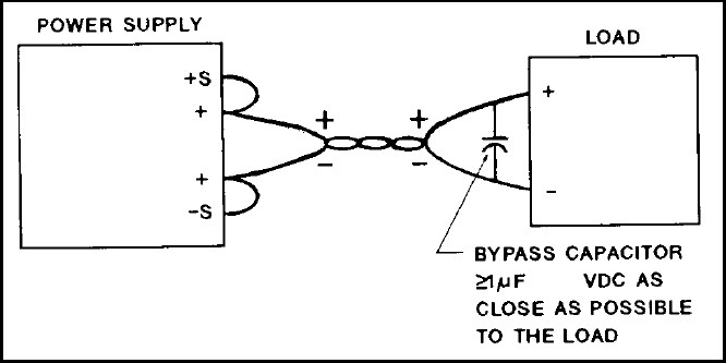
The PARD specifications in Table 1-1 apply at the power supply output terminals. However, noise spikes induced in the
load leads at or near the load may affect the load although the spikes are inductively isolated from the power supply. To
minimize voltage spikes at the load, connect a bypass capacitor as shown in Figure 3-2. With this setup, peak-to-peak noise
at the load can actually be reduced to a level below the value specified at the power supply output terminals.
500
Figure 3-2. Connecting a Bypass Capacitor
Overvoltage Protection (OVP)
The overvoltage trip point is adjusted at the front panel. The approximate trip voltage range is from zero volts to
approximately 107% of maximum rated voltage of the power supply. When the OVP circuit trips, the power supply output
is disabled and delivers no output power, and the OVP and UNREGULATED indicators turn on.
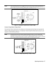
Adjustment. OVP is set by the recessed single-turn OVP ADJUST potentiometer on the front panel. Rotating the control
clockwise sets the trip voltage higher. (It is set to maximum at the factory.) When adjusting the OVP trip point, the
possibility of false tripping must be considered. If the trip voltage is set too close to the supply’s operating voltage, a
transient in the output would falsely trip the OVP. For this reason it is recommended that the OVP trip voltage be set higher
than the output voltage by at least 1 volt. To adjust the OVP trip voltage, proceed as follows:
a. Turn on supply and hold DISPLAY OVP pushbutton in.
b. Insert a small-blade screwdriver through hole in front panel and adjust OVP trip voltage to desired level.
OVP Reset. To reset OVP, turn the LINE switch off and then back on. The cause of the overvoltage must be removed
before the OVP circuit is reset or the circuit will trip again immediately. If the OVP circuit trips continuously check the load
and the trip voltage.
Protective Shutdown
Protective circuits within the power supply may limit or turn off the output in case of abnormal conditions. The cause of the
protective action can be determined by observing the front panel indicators (lights and meters).
Unregulated. If an overrange condition exists (load tries to draw more power than the supply can deliver), the
UNREGULATED indicator turns on and both the CV and CC indicators are off. The product of the VOLTS and AMPS
displays will exceed the maximum output power of the supply. Also, if the power supply output is disabled by protective