


38 Operating Instructions
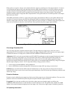
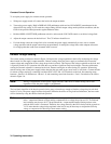
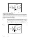
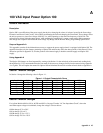
Figure 3-9. Optional Voltage Divider for Program Source
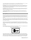
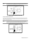
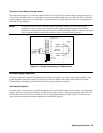
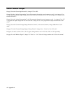
Constant Current Output, Resistance Control.
The setup shown in Figure 3-10 allows the output current to be varied by using an external resistor to program the supply. A
programming resistor variable from 0 to 4000 ohms produces a proportional output current from zero to full scale. Note that
fixed resistors may be connected in series and/or parallel with the variable programming resistor to set lower and/or upper
output current limits. The resultant programming resistance is the sum of the series/parallel resistor combination, and must
be between 0 and 4000 ohms. For example, a 2000 ohm resistor connected in series with the variable programming resistor
will set the lower limit for output current at one-half full scale.
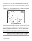
Caution: If the programming terminals (IP to P) become open circuited during resistance programming the
output current will tend to rise above rating. The power supply will not be damaged if this occurs, but
the user’s load may be damaged. If there is a possibility that the programming leads may be opened, it
is suggested that the optional resistor be connected directly across terminals IP and
P, as shown in
Figure 3-10. The value of this resistor should be selected to limit the output current to the maximum
that the load can handle without damage. For example, if the load can handle half the current rating of
the power supply, a 2000 ohm resistor should be connected from IP to
P. If this resistor is used,
the actual resistance value programming the supply is the parallel combination of the two resistors.
Figure 3-10. Resistance Programming of Output Current
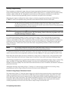
= Handle
= Handle