


36 Operating Instructions
Analog Programming
These instruments can obtain their output voltage and current programming information from three distinct sources: 1)
locally from the front panel, 2) remotely from an external isolated, voltage source or, 3) remotely from an external isolated,
resistance. Mode switches B1, B2, .through B6, located on the rear of these products, enable the user to make these
selections. The remote analog programming signals are connected to rear-panel screw-on terminals.
When the power supply is configured for remote voltage or resistance programming, the front panel VOLTAGE or
CURRENT controls of the parameter being controlled are disconnected and have no effect on the output.
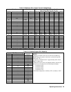
Note: Switches B1, B2 and B3 are for selecting the programming source for the output current. Switches B4, B5
and B6 select the programming source for the output voltage. The source of the Constant Current
programming information is selected independently from the source of the Constant Voltage programming
information. Both can be done at the same time.
Caution: The common terminal ( P) is internally connected to the minus (-) output terminal. If either output is
grounded, the external programmer MUST be floating. Failure to float the programmer may result
in significant damage to the power supply.
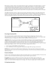
For resistance programming, internal CV and CC current sources supply 1.25 mA currents through the programming
resistors to create programming voltages for the power supply. A resistance of 0 to 4 K ohms will program the output
voltage or current from 0 to full scale. A variable resistor can control the output over its entire range. Or, a variable resistor
connected in series and/or parallel with a fixed resistor can have its control restricted to a limited portion of the output
range. Alternatively, a switch can be used to select fixed values of programming resistance to obtain a set of discrete
voltages or currents.
Note: The switching configuration used may require make before-break contacts to avoid producing the output
voltage transients caused by momentarily opening the programming terminals.
To maintain the temperature and stability specifications of the power supply, any resistors used for programming must be
stable, low-noise resistors with a temperature coefficient of less than 25ppm per
°
C and a power rating of at least 1/2 watt.
Both voltage and current outputs can also be controlled by a voltage source. A voltage of 0 to 5 volts programs the output
voltage or current from zero to full scale. Voltage sources of more than 5 volts can be scaled down to the proper range.
The following paragraphs discuss in greater detail the methods of remotely programming the output voltage or current using
either a resistance or voltage input. Whichever method is used, the wires connecting the programming device must be
shielded to reduce noise pickup. The outer shield of the cable should not be used as a conductor, and should be connected to
ground at one end only.
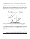
Although the following setup drawings (Figure 3-7 through 3-11) show the supply strapped for local sensing, analog
programming and remote voltage sensing do not interact and may be used simultaneously.
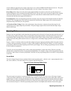
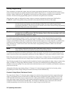
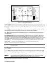
Constant Voltage Output, Resistance Control.
The setup shown in Figure 3-7 allows the output voltage to be varied by using an external resistor to program the power
supply. A programming resistor variable from 0 to 4000 ohms produces a proportional output voltage from zero to full
scale. Note that fixed resistors may be connected in series and/or parallel with the variable programming resistor to set
lower and/or upper output voltage limits. The resultant programming resistance is the sum of the series/parallel resistor
combination, and must be between 0 and 4000 ohms. For example, a 2000 ohm resistor connected in series with the
variable programming resistor will set the lower limit for output voltage at one-half full scale.