


32 Operating Instructions
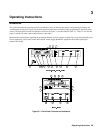
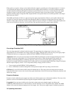
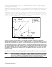
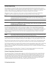
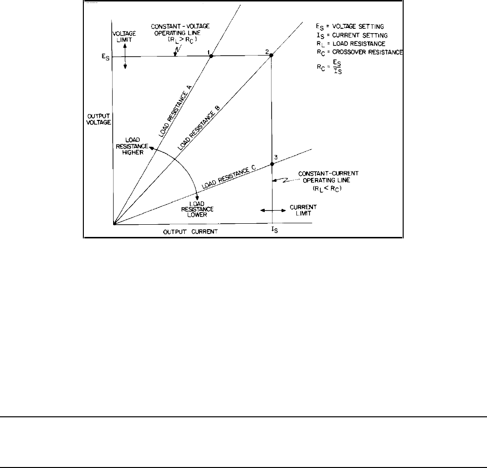
crosses the operating locus at point 1. Point 1 is on the part of the operating locus defined by the voltage setting, so the
power supply operates in CV mode.
Similarly, the line representing load resistance C, the lowest load resistance shown on the graph, crosses the operating locus
at point 3. Point 3 is on the part of the operating locus defined by the current setting, so the power supply operates in CC
mode.
Load Resistance B equals the crossover resistance for the particular combination of voltage and current settings shown on
the graph. Either the CV or CC LED will light. If the load resistance increases, the voltage setting decreases, or the current
setting increases, the power supply will operate in CV mode. Conversely, if the load resistance decreases, voltage setting
increases, or current setting decreases, the power supply will operate in CC mode.
Figure 3-4. Determining Operating Point
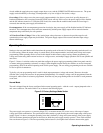
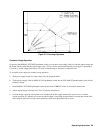
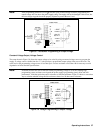
In Figure 3-5, the voltage and current settings are high enough that the rectangular operating locus is cut off by the
maximum output power boundary of the power supply. For the load resistance A, the power supply operates in CV mode at
the voltage and current values for point 1. Similarly, for load resistance D the power supply operates in CC mode at point 4.
For load resistance between B and C, the operating point will be on the maximum output-power boundary between points 2
and 3, and the UNREGULATED indicator will be on. The VOLTS and AMPS displays will indicate the voltage and current
being supplied to the output. (The product of the two readings will exceed rated output power of the supply.) Note that the
actual boundary is beyond the specified minimum boundary. The UNREGULATED indicator will light only if the actual
boundary is exceeded.
The supply can operate in the overrange region for sustained periods without being damaged. However, the supply is not
guaranteed to meet specifications in overrange. Output ripple increases substantially and regulation is seriously degraded.
Note: Under certain conditions of line and load, it is possible for the supply to provide more than rated output
power and still maintain regulation. If this occurs, the unit will operate normally and the OVERRANGE
indicator will be off. However, the slightest change in either line or load may cause the unit to go out of
regulation. Operation of the unit beyond the rated-output-power boundary is not recommended.