


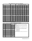

Operating Instructions 37
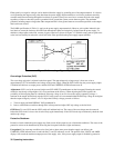
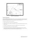
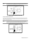
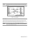
Note: If the programming terminals (VP to P) become open circuited during resistance programming, the
output voltage will rise above the power supply rating. The supply will not be damaged if this occurs, but
the overvoltage trip point should be properly adjusted to protect the user’s load.
Figure 3-7. Resistance Programming of Output Voltage
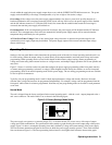
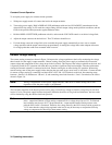
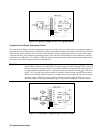
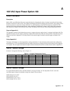
Constant Voltage Output, Voltage Control.
The setup shown in Figure 3-8 allows the output voltage to be varied by using an external voltage source to program the
supply. A voltage source variable from 0 to + 5 volts produces a proportional output voltage from zero to full scale. The
static load on the programming voltage source is less than 5
µ
A. A source resistance of less than 10k is necessary to avoid
degradation of offset and drift specifications.
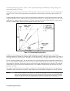
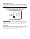
Note: If external resistors are used to limit the remote-programming voltage to 5Vdc, the resulting high
programming-source resistance can degrade the power supply’s programming speed, offset and drift
performance. Limit the equivalent source resistance to 10k ohm maximum. Figure 3-9 shows a convenient
way to calculate suitable voltage-divider resistance values for a 5k ohm source resistance.
Figure 3-8. Voltage Programming of Output Voltage
= Handle
= Handle