


26 Operating Instructions
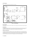
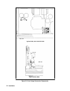
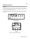
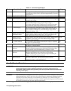
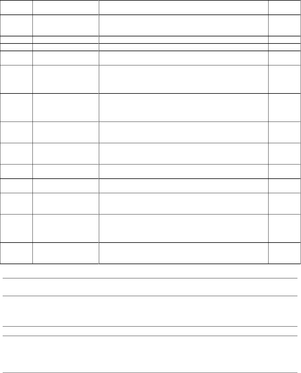
Table 3-1. Controls and Indicators
Number Controls/Indicators Description Page
1 LINE Switch Pressing at the top of the switch applies ac mains voltage to the units
bias and power circuits. Unit is operational approximately 3 seconds
after power on.
27
2 VOLTAGE CONTROL Clockwise rotation increases the output voltage, 0 to full scale Vdc. 27
3 CURRENT CONTROL Clockwise rotation increases the output current, 0 to full scale Adc. 27
4 OVP ADJUST The recessed, single-turn screwdriver control sets the overvoltage
protection trip voltage
30
5 Voltage Display A 3-1/2-digit display with automatically positioned decimal point
that can indicate output voltage, output voltage setting or
overvoltage shutdown setting. During an error condition, the output
may exceed the display range and the display will indicate + OL.
27
6 Current Display A 3-1/2 digit display with automatically positioned decimal point
that can indicate output current or output current setting. During an
error condition, the output may exceed the display range, and the
display will indicate + OL.
27
7 DISPLAYS SETTINGS
Pushbutton Switch
Causes numeric displays to indicate programmed voltage and current
values, rather than actual output values; allows both settings to be
made without the necessity of opening or shorting load.
33, 34
8 DISPLAY OVP
Pushbutton Switch
Causes VOLTS display to indicate OVP trip voltage, AMPS display
is blanked; allows setting to be made without changing output
settings or load connections
33, 34
9 CV Status Indicator CV (Constant Voltage) indicates that the power supply is regulating
its output at a constant voltage.
33
10 CC Status Indicator CC (Constant Current) indicates that the power supply is regulating
its output at a constant current.
34
11 UNREGULATED Status
Indicator
UNR (Unregulated) indicates that the power supply is operating
beyond its maximum output power specification and that the output
is not regulated or has been shutdown by a protective circuit.
31, 32
12 OVERVOLTAGE Status
Indicator
OV (Overvoltage) indicates that the power supply output has been
shut down and latched by the occurrence of an overvoltage
condition. Removing the cause of the overvoltage and turning the
supply off and back on will reset the unit.
31
13 OVERTEMPERATURE
Status Indicator
OT (Over temperature) indicates an overheating condition on either
the diode or FET boards. OT automatically resets when the
temperature drops to a safe operating level.
31
Turn-On Checkout Procedure
WARNING: Before the instrument is turned on, all protective earth terminals, extension cords, and devices
connected to the power supply should be connected to a protective earth ground. Any
interruption of the protective earth grounding will cause a potential shock hazard that could
result in personal injury.
Caution: This instrument can be damaged by electrostatic discharge into the control connectors, or the switches
on the rear panel even while the unit is turned on. Do not cause an electrostatic discharge into these
connectors and switches (which may occur when they are touched). Also, consistent with good
engineering practice, leads attached to customer accessible signal/monitoring ports should be twisted
and shielded to maintain the instruments specified performance.
The following procedure ensures that the supply is operational, and may be used as an incoming inspection check.