


18
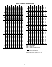
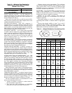
Table 13 — Minimum Gpm Required for
Water-Cooled Heads and/or Oil Cooler
(Based on 30° F Rise)
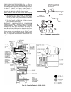
SAFETY RELIEF VALVES — All 5H compressors are
equipped with built-in safety relief valves that are factory set to
relieve from discharge to suction side of the compressor at a
pressure differential of 350 psi.
Safety relief valves that relieve at a 400 psi pressure differ-
ential are factory installed on the 5F60 compressor but are not
available with smaller 5F compressors.
SUCTION STRAINERS — Each 5F,H compressor is
equipped with one or 2 suction strainers located in the suction
manifold. On new installations, felt filters should be used in
suction strainers to trap foreign material left after installation.
After 50 hours of use, these felt filters must be removed. See
5F,H Installation Instructions for further details.
OIL SAFETY SWITCH — An oil safety switch is provided
as standard with all compressors except 5F20 and 5F30. This
switch is optional equipment on 5F20 and 5F30 compressors.
This switch will shut off the compressor before high oil
temperatures or lack of oil causes loss of oil pressure which can
result in compressor failure. As a safety feature, this switch
must be reset manually after cutout.
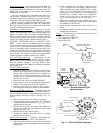
OIL SEPARATORS — Oil separators in the hot gas discharge
line are not recommended for general use. However, there are
systems where protection afforded by a separator is desirable,
notably systems employing flooded evaporators or refrigera-
tion systems with long system piping. For a more complete
discussion see Carrier’s System Design Manual.
CRANKCASE OIL HEATERS — Crankcase oil heaters are
available for all 5F,H compressors. Heaters keep the crankcase
warm during off cycles and thus minimize refrigerant absorp-
tion in the oil. Crankcase heaters are recommended for CFC or
HCFC refrigerant applications and are required for HFC refrig-
erant applications with POE lubricants. Refer to the 5F,H
Installation Instructions for installation and wiring.
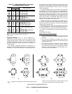
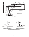
INTERCONNECTION OF COMPRESSORS — All 5F,H
compressors are furnished with removable handhole cover
plates on each crankcase. When field interconnection is desired
on 5F40 through 5H86 compressors, cover plates can be
removed and replaced by special cover plates with tapped open-
ings. These tapped cover plates have connections for both oil
and gas equalizing lines. For interconnection of 5F20 and 5F30
compressors, use the opening for the oil sight glass (see 5F,H
Installation Instructions). Cover plates for interconnection are
standard equipment on 5F120 and 126 compressors.
Many refrigeration systems utilize oil management compo-
nents such as an oil separator, oil reservoir and floats. The oil
level control float an be installed in the sight glass connection
in the 5F,H handhole cover plate.
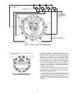
VIBRATION ISOLATORS — A standard vibration isolation
package is available for each 5F,H compressor. This consists of
a standard rubber-in-shear and compression type mounting that
gives an average static deflection of approximately
1
/
8
in. and
provides reasonably good vibration isolation at 1750 rpm.
The use of vibration isolators is recommended for all com-
pressor and condensing units because:
1. Transfer of vibration to structure is reduced when the
units are installed on upper floors.
2. They limit drive shaft misalignment on installations
where units are bolted to an uneven concrete floor.
Vibration isolators giving approximately
3
/
8
-in. deflection
are available for superior isolation or if the compressor is run at
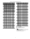
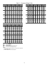
slower speeds. Tables 14 and 15 provide an estimated weight
distribution on legs of a compressor or condensing unit when
used with a normal horsepower motor.
MUFFLERS — Four standard mufflers cover the entire model
range of 5F,H compressors. It is recommended that these
mufflers be installed when compressors are used with remotely
located water-cooled or evaporative condensers.
Mufflers are not usually necessary with smaller 5F
compressors and their use is recommended only when quiet
operation is required.
Each piping package to convert 5H compressor units to
condensing units includes a standard muffler of appropriate
size.
Pressure drop through mufflers is about
1
/
2
psi at 40 F
suction and 105 F discharge with following loadings: 5 tons
with 5F20 muffler, 15 tons with 5F40 muffler, 35 tons with
5H40 muffler and 100 tons with 5H120 muffler.
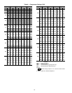
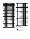
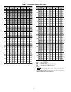
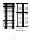
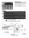
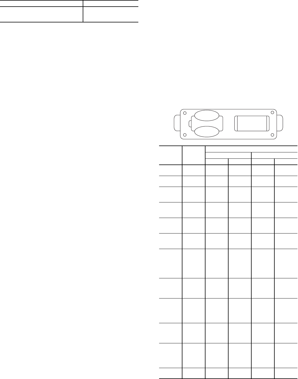
Table 14 — Weight Distribution, Condensing Units
*Oversize frame.
COMPRESSOR GPM
5F
2-3
5H (4, 6 and 8 Cylinders)
6
5H (12 Cylinders)
8
COMPR
COND
SIZE
WEIGHT DISTRIBUTION (lb)
Belt Drive Direct Drive
A or D B or C A or D B or C
5F20
20 138 115 ——
30 148 125 ——
5F30
20 163 135 ——
30 170 148 ——
5F40
30 280 220 ——
40 325 263 305 240
60 345 285 325 265
5F60
40 365 305 ——
60 406 345 360 305
027 ——470 430
5H40
60 525 423 ——
027 585 478 555 450
043 665 603 580 505
5H46
043 ——580 505
054 ——610 535
070 ——625 550
5H60
027 693 570 ——
043 745 625 710 590
054 825 818 755 635
054* 915 823 ——
070 930 833 765 645
084 ——960 865
5H66
054 ——755 635
070 ——765 645
084 ——690 865
097 ——1030 935
5H80
043 1023 803 ——
054 1065 848 985 900
070 1075 858 995 910
084 1163 943 1080 995
097 1185 1018 1150 1065
5H86
070 ——995 910
084 ——1030 995
097 ——1150 1065
127 ——1300 1215
5H120
054 1335 1008 ——
070 1350 1023 1280 1080
084 1425 1098 1340 1140
097 1493 1163 1385 1185
127 ——1535 1335
5H126
097 ——1325 1185
127 ——1535 1335
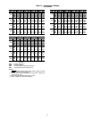
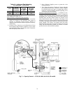
MOTOR
C
B
COMPR
D
A