


21
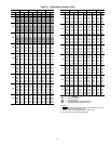
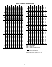
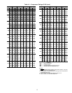
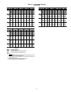
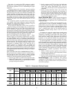
Table 17 — Initial and Final Unloading
Oil Pressures — 5F20, 5F30
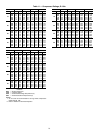
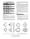
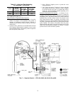
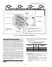
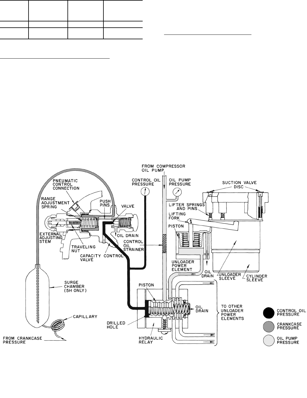
5F40 THROUGH 5H86 (Fig. 7)
Major Elements of Capacity Control Systems:
1. Capacity Control Valve: Function is to raise or lower the
control oil pressure to the hydraulic relay piston in
response to refrigerant suction pressure. Increase in
suction pressure increases control oil pressure in the hy-
draulic relay.
2. Hydraulic Relay: Function is to feed lubrication oil from
the oil pump at full pressure in sequence to one or more
power elements. Relay is activated by control oil pressure
from the capacity control valve.
3. Power Element: Supplies power to operate the valve
lifting mechanism.
4. Valve Lifting Mechanism: Consists of a sleeve and push
pin assembly around each controlled cylinder, designed
to hold the suction valve open, or to permit the valve to
remain in a normal operating position depending on its
actuation by the power element.
Principle of Operation of the System
— A decrease in suc-
tion gas pressure, which necessitates a decrease in compressor
capacity, causes the range spring to open the capacity control
modulating valve. This allows control oil to relieve from the
hydraulic relay and thus reduces control oil pressure in the
relay. With reduced control oil pressure, the spring in the
hydraulic relay moves a piston and thus lubrication oil from the
oil pump is prevented from flowing to a particular deactivated
power element. This relieves oil pressure from the power
element allowing the spring in the power element to move the
lifting fork and unload the cylinder. An increase in suction
pressure reverses action and loads cylinders.
COMPR
NO. OF
CONTROLLED
CYLINDERS
START TO
UNLOAD
OIL PRESS.
(psi)
COMPLETELY
UNLOADED
OIL PRESS.
(psi)
5F20
1 19.8 13.0
5F30
1 30.0 20.2
2 19.8 13.0
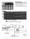
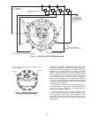
Fig. 7 — Capacity Control — 5F40, 60; 5H40, 46, 60, 66, 80 and 86