


2
OPEN-DRIVE COMPRESSORS
These compressors are designed to operate with Refriger-
ants 12, 22, 134a, 502, or 507/404A. See Table 1.
Operating Requirements —
Satisfactory operation of
a reciprocating compressor depends on 3 fundamental
requirements:
1. Prevention of excess discharge temperature.
2. Adequate compressor lubrication.
3. A clean and dry system.
Discharge Temperature —
The temperature at the
discharge valves within the cylinders is a controlling factor.
Some cooling of the discharge gas occurs before reaching the
discharge stop valve, thus when water-cooled heads are used,
this cooling is greater than it is without water cooling. To pre-
vent excessive temperature at the compressor discharge valves,
the following temperatures, when measured immediately
following the discharge stop valve, must never be exceeded:
For nonwater-cooled heads . . . . . . . . . . . . . . . . . . 275 F max
For water-cooled heads . . . . . . . . . . . . . . . . . . . . . 250 F max
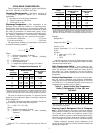
The approximate discharge gas temperature can be found
by using the following equation:
Where:
T
2
= Discharge temperature, F absolute
T
1
= Suction temperature, F absolute (including
superheat)
P
2
= Discharge pressure, psia
P
1
= Suction pressure, psia
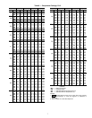
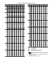
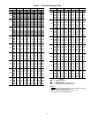
N = Compression exponent of the gas (see Table 2)
Table 2 — Compression Exponent “N”
*For R-134a and R-507/404A refer to the Carlyle Compressor Selection
program (http://www.carlylecompressor.com/TechnicalInfo/Carwin.htm) to
determine discharge temperature. The selection program can also be
used for R-22 and R-502 in place of the discharge temperature formulas.
The value of compression exponent “N” depends upon the
properties of gas compressed, degree of cooling in compressor
jacket, leakages, etc.
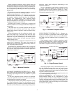
To simplify discharge temperature calculations, the preced-
ing formula may be stated in the following form:
T2 = [(460 + T1) x C] – 460
Where:
T2 = Discharge temperature, F actual
T1 = Suction gas temperature, F actual (including
superheat)
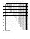
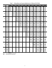
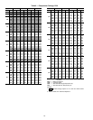
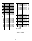
Values for “C” at various compression ratios are listed in
Table 3.
Table 3 — “C” Factors
*For R-134a and R-507/404A refer to the Carlyle Compressor Selection
program (http://www.carlylecompressor.com/TechnicalInfo/Carwin.htm) to
determine discharge temperature. The selection program can also be
used for R-22 and R-502 in place of the discharge temperature formulas.
Example:
Refrigerant 12
Factor C = 1.33
Suction Temperature, T1 = 0° F saturated, superheated
to 65 F
Solution:
T2 = [(460 + 65) x 1.33] – 460
= 698 – 460
= 238 F
Although exponents are shown for high compression ratios,
these are for information only. Rating tables define allowable
selection and operation limits.
High Compression Ratio —
Avoid compressor oper-
ation at compressor ratios exceeding those covered in the rating
tables. For operating conditions outside the limits shown in
these tables, use 2-stage compression. Care must be taken to
prevent the compressor from pulling down to levels outside the
rating tables.
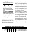
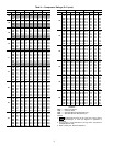
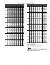
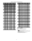
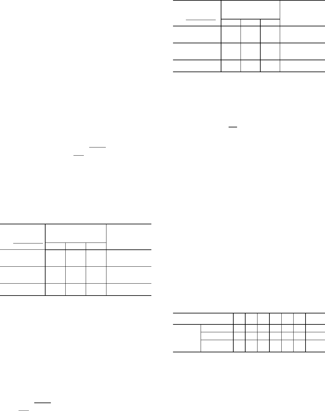
Suction Gas Superheat —
Excessive suction gas super-
heat will result in abnormally high discharge temperatures,
which must be avoided. When using Refrigerants 12, 134a, 502,
and 507/404A it is recommended that the actual suction gas
temperature not exceed the values in Table 4.
Table 4 — Actual Suction Gas Temperature
Limits (F) Refrigerants 12, 134a, 502, and
507/404A*
*With Refrigerant 22, the suction gas superheat should never exceed
25 F for continuous operation.
Keeping Liquid Refrigerant Out of Compres-
sor —
Liquid refrigerant, or excessive amounts of entrained
liquid particles in suction gas must be kept out of the compres-
sor by proper system design and compressor control. Under
operating conditions, presence of unevaporated liquid refriger-
ant in the compressor tends to break down oil film on cylinder
walls, resulting in increased wear and loss of machine capacity.
During compressor operation, proper adjustment of the
expansion valve will prevent excessive amounts of liquid from
entering the compressor.
N – 1
T
2
= T
1
(
P2
)
N
P1
COMPRESSION
RATIO
WITHOUT
WATER-COOLED
HEADS*
WITH
WATER-COOLED
HEADS
R-22
=
Discharge
Suction psia
R-12 R-22 R-502
2
1.216 1.325 1.234 1.240
3
1.191 1.258 1.216 1.218
4
1.177 1.240 1.206 1.205
5
1.172 1.234 1.197 1.199
6
1.166 1.232 1.190 1.196
8
1.160 1.228 1.178 1.192
10
1.155 1.225 1.169 1.187
12
1.150 1.224 1.161 1.182
N – 1
C =
(
P2
)
N
P1
COMPRESSION
RATIO
WITHOUT
WATER-COOLED
HEADS*
WITH
WATER-COOLED
HEADS
R-22
=
Discharge psia
Suction psia
R-12 R-22 R-502
2
1.14 1.17 1.13 1.15
3
1.19 1.25 1.22 1.22
4
1.23 1.31 1.27 1.27
5
1.26 1.36 1.30 1.31
6
1.29 1.40 1.33 1.34
8
1.33 1.47 1.37 1.40
10
1.36 1.53 1.40 1.44
12
1.38 1.57 1.41 1.47
Compression Ratio
P
2
= 8
P
1
SATURATED SUCTION
GAS TEMP
–60 –50 –40 –30 –20 –10
0 AND
ABOVE
Actual
Suction
Gas Temp
R-12
— — 35 45 55 65 65
R-134a
—————— 65
R-502
R-507/404A
25 35 45 55 65 65 65