


23
Control Pressurestats
— Dual pressurestats are furnished with
all 5F,H compressors. They are often referred to as high- and
low-pressure cutouts. Their function is to cut the circuit to the
holding coil of the compressor motor starter when pressure
setting limits are exceeded.
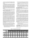
The high pressurestat has an operating range from 50 to
450 psig with a differential range from 170 to 235 psig (adj).
The low pressurestat has an operating range from 20 in. Hg to
60 psig and a differential range from 60 to 90 psig (adj).
Pressurestat settings should be adjusted on the job to meet
particular operating conditions for which the compressor(s)
have been selected. Directions for setting these pressurestats
are in the 5F,H Installation Instructions.
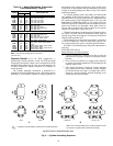
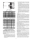
Permanently Unloaded Cylinders
— Operation of an open-
drive compressor with its cylinders permanently unloaded
requires field modification. The 5F60, 5H40 and 5H60 com-
pressors can operate with one cylinder unloaded; 5H80 and
5H120 compressors can operate with 2 cylinders unloaded.
Compressors are modified by removing the suction valve and
suction valve springs from the cylinder(s) shown in Fig. 4.
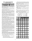
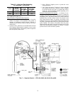
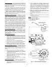
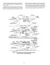
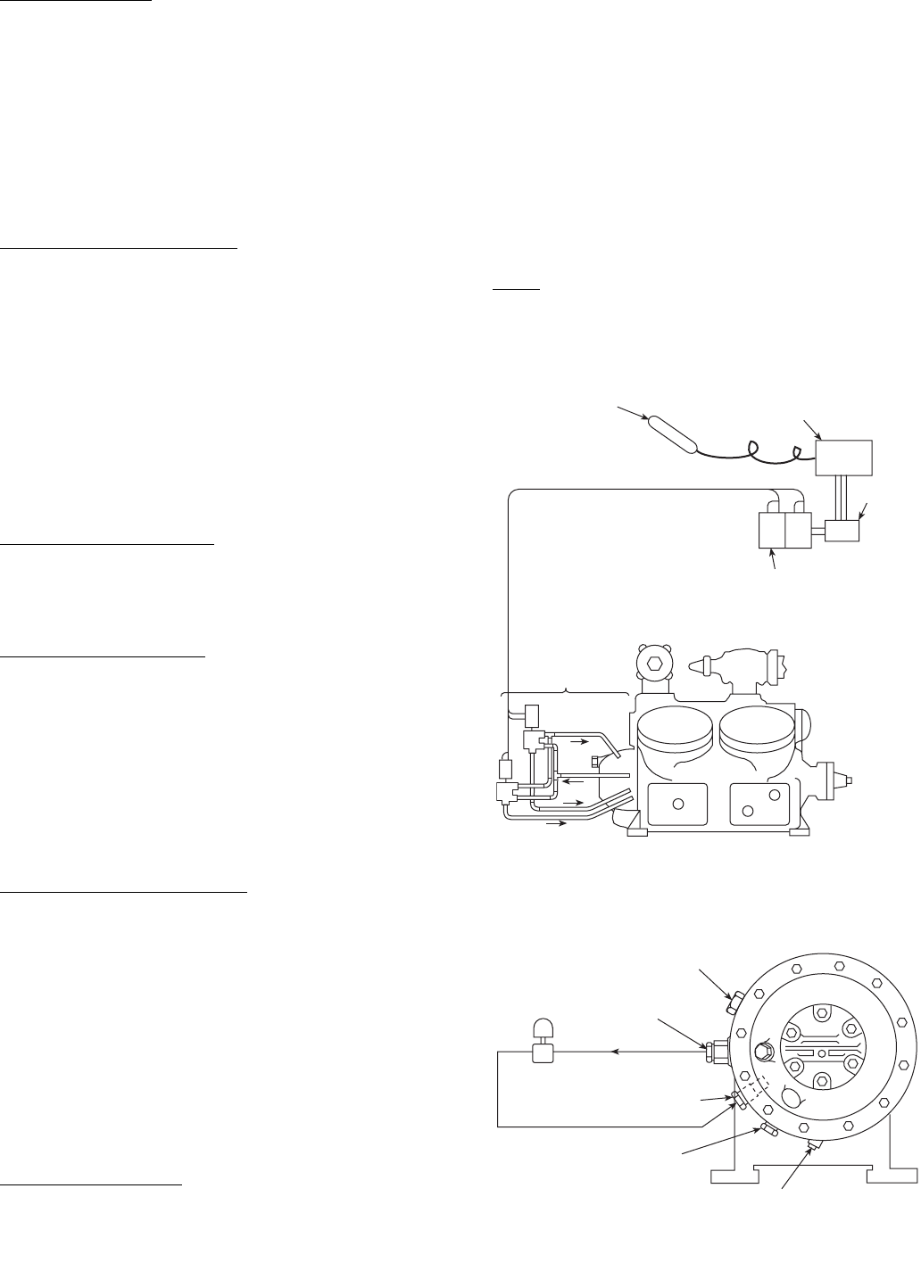
ELECTRIC SOLENOID VALVE CAPACITY CON-
TROL — Closer control of a conditioned space or medium
can be realized by activating the cylinder unloaders directly in
response to an external step controller activated by solenoid
valves. A temperature sensing controller activates the electric
solenoid valves. Refer to Fig. 10 for an operating concept using
an external electric solenoid-type capacity control. All compo-
nents external to the compressor must be field supplied. Modi-
fications required for standard sequence are as follows:
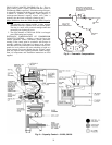
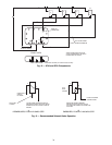
5F20 and 5F30 Compressors
— Modifications are not
required to the 5F20 and 5F30 compressors. See Fig. 4 and 11.
Securely attach a ported solenoid valve to compressor to mini-
mize line vibration. Connect a
1
/
4
-in. steel tubing or high-
pressure flexible hose, KA73RR025, between the compressor
and solenoid valve.
5F40 and 5F60 Compressors
1. Remove the capacity control handhole cover. Remove the
hydraulic relay and all tubing. As shown on Fig. 12, drill
and tap 3 holes on the bottom side of the cover and 2 on
the front. No hole is required at point A on 5F40 com-
pressors. Plug 5 cover holes that connected cover to the
relay. Plugs are
1
/
8
NPT.
2. Install cover with a new cover gasket 5F40-1042.
3. Mount solenoid valves on a sturdy bracket attached to the
handhole cover using stud bolts on the compressor.
4. Connect external oil lines as shown in Fig. 12 and 13.
Steel tubing and compression fittings are recommended.
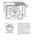
5H40 Through 5H86 Compressors
— Standard compressors
5H40 through 5H86 built after Serial No. G103460 (July 1971)
may be modified for electric solenoid unloading without addi-
tional machining. Proceed as follows: (See Fig. 4, 13, 14,
and 15).
1. Remove pump end cover only from the compressor.
2. Using the pump end cover gasket (Part No. 5H40-1423)
as a guide, make a blank metal disc (
1
/
32
to
1
/
16
-in. thick),
making holes for bolts only.
3. Reinstall the pump end cover using 2 new 5H40-1423
gaskets, one on each side of the blank disc. This isolates
the capacity control cover.
4. Mount solenoid valves and run oil lines.
5. To minimize vibration, mount the valves on a bracket
attached to the compressor.
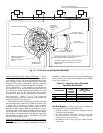
5H120, 126 Compressors
— Following modifications are
required to electrically unload 5H120, 126 compressors.
1. After closing the compressor service valves and reducing
refrigerant pressure to the atmosphere, remove pump end
bearing head.
2. Remove hydraulic relay assembly by removal of two
5
/
16
-in.-18 socket head screws. Make a blank metal disc
using a hydraulic relay gasket (5H120-3351) as a guide.
Using
1
/
32
to
1
/
16
-in. thick metal, cut holes in the disc for
dowel pins only. (Do not cut five
9
/
32
-in. diameter holes.)
Reinstall relay assembly using 2 new 5H120-3351
gaskets, one on each side of the metal disc. Torque
5
/
16
-in. socket head screws evenly to 16 to 20 lb-ft.
3. Reinstall the bearing head using extreme care not to
damage the oil pump tang. Align with recess in the end of
the crankshaft. Do not force on.
4. Mount solenoid valves and run oil lines. See Fig. 4, 13,
and 16.
5. To minimize vibration, mount the valves on a bracket
attached to the compressor.
Valves
— The following 3-way valves have been used in the
field and are listed as a guide:
• Alco Controls No. 702RA001.
• Also Controls No. S608-1.
• Sporlan Type 180.
SENSING
BULB
MOTOR
2-STEP SEQUENCE
CONTROLLER
SOLENOID
VALVE
CLUSTER
PROPORTIONING TYPE
ELECTRIC CONTROLLER
1
2
TO OIL COOLER
MAGNETIC PLUG
OIL FILLER PLUG
1/4” NPT OIL PUMP
PRESS. CONN.
SOLENOID
VALVE
3/8” NPT OPENING TO
CRANKCASE
Fig. 10 — External Solenoid-Type
Capacity Control
Fig. 11 — 5F20 and 5F30 Compressor