


39
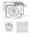
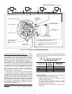
Water Circuiting Arrangements —
The water cir-
cuiting arrangement selected for 5F and 09RH condensers
depends on available condenser water pressure, temperature,
quantity and source. Refer to Table 32.
Refer to the Carrier System Design Manual for specific
information and recommendations for refrigerant and water
piping.
Economics —
Selection of a condenser requires balancing
of certain economic variables, including:
1. First cost of compressor-condenser combination.
2. Operating costs.
3. Ratio between power costs and water costs.
Where first cost is the most important consideration, the
best combination of compressor and condensers has the lowest
total equipment cost.
If owning and operating costs are important, combination
must be selected on basis of both considerations.
A condenser selection that permits operation of the system
at a low condensing temperature, results in the lowest compres-
sor motor brake horsepower and consequently, lowest operat-
ing cost. A condenser selection that is heavily loaded requires
the compressor to operate at a higher condensing temperature
and results in higher compressor motor brake horsepower and
operating cost.
For a given compressor-condenser combination, selection
of a condensing temperature may depend on a ratio between
power costs and water costs, on quantity of water available,
on condensing temperature required to achieve compressor
capacity, or a requirement to remain within allowable loading
on a given motor size.
Condenser Performance with Ethylene Gly-
col —
Increased use of closed circuit cooling towers has led
to a corresponding increase in the need for shell and tube con-
denser ratings for use with ethylene glycol. When towers are
installed outdoors, a brine solution is required for freeze protec-
tion during winter operations.
In most outdoor installations, specifications will call for a
percentage of concentration of ethylene glycol or other brine
solution. If concentration is not specified, it may be the choice
of the contractor to determine a percentage of glycol concentra-
tion to ensure against freeze-up during winter minimum design
ambients.
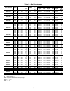
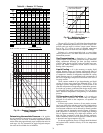
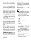
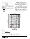
To perform simplified selection, use Fig. 22 to convert a
condenser water rating to a brine rating.
EXAMPLE:
Assume that a building with a year-round cooling load has a
cooling requirement of 120 tons during summer design condi-
tions. Chilled water design temperatures are 54 F entering to
44 F leaving, and for summer duty, the condenser water is
based on 85 F and a 10 degree rise.
From product literature, selected unit will deliver 121 tons
at 105.8 F saturated discharge temperature (SDT) and has
153 tons of heat rejection.
Determine condenser loading factor by use of following
formula:
Where: EWT — Entering Water Temperature
LF — Loading Factor
THR — Total Heat Rejection
The 85 F value is return water temperature from closed cir-
cuit cooler.
Entering condenser rating data at loading factor of 7.9,
300 gpm are required to maintain design condensing tempera-
ture. Next, determine the rise by:
If a more precise rise is desired, go back and assume a
slightly different condensing temperature, recalculate the load-
ing factor and rise and repeat the procedure until a final balance
is found.
For this example, condenser water pressure drop is approxi-
mately 9.4 ft for the design 300 gpm flow rate. Using Fig. 22,
flow rate correction can be determined for any glycol concen-
tration versus water in shell and tube condensers.
Continuing with example, assume specifications required
protection against freeze-up at an ambient of 0° F. (A glycol
concentration that provides protection between 10 and 15 de-
grees below expected minimum ambient has been the design
criteria for many years.)
In a condenser system, the use of proper ethylene glycol
brine concentration is important because of the phenomenon
that commonly published freeze points are not freeze points but
are the point of crystallization where the first crystals begin to
form. Actual freezing into a solid occurs at much lower
temperatures. For example, freeze point of 20% ethylene
glycol is given as +16 F but does not become a solid until it
reaches –50 F; 35% ethylene glycol with a freeze point of –6 F
does not become solid until it reaches –120 F. Consequently,
20% glycol solution will take care of most domestic applica-
tions and 35% brine should satisfy the rest. The lowest con-
centration of brine will be the most efficient and result in
considerable energy conservation.
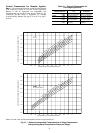
Entering Fig. 22 at 0° F crystallization point, necessary
concentration of glycol is either 32.5% by weight or 30% by
volume. Next, determine glycol flow rate:
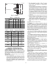
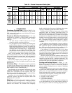
Table 32 — Condenser Water Circuiting
LF =
THR
SDT – 1.5 line loss – EWT
=
153
(105.8 – 1.5) – 85
=
153
= 7.9
19.3
Rise =
THR x 24
Gpm
=
153 x 24
= 12.2 degrees
300
Glycol Flow Rate =
THR (tons) x Glycol Factor (GF)
Rise
WATER CIRCUITING
ARRANGEMENTS
CONDENSER SIZE
CONDENSER
CHARACTERISTICS
NORMAL USE
Double Circuit
4 Passes
3 Passes
5F20, 5F30
5F40, 5F60
All 09RH
High Water Quantity
Low Pressure Drop
Cooling Tower
Single Circuit
8 Passes
6 Passes
5F20, 5F30
5F40, 5F60
All 09RH
Low Water Quantity
High Pressure Drop
City or Well Water