


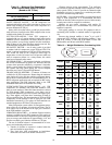
22
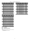
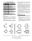
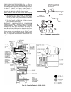
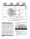
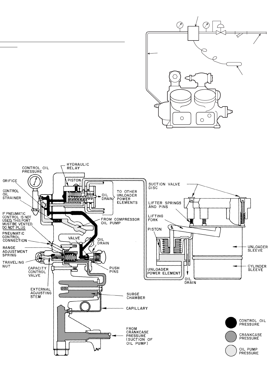
5H120, 5H126 CAPACITY CONTROL (Fig. 8) — This ca-
pacity control system is slightly different from the system on
5F40 through 5H86 compressors. Unloaded starting and capac-
ity reduction is obtained by holding open the suction valves of
a number of cylinders. For capacity control purposes, a
suction-pressure-actuated capacity control valve pilots a
hydraulic relay that loads or unloads cylinders in pairs.
Major Difference from the 5F40 through 5H86 Capacity
Control:
1. The hydraulic relay design provides a wider pressure
differential between cylinder cut-in and cutout points.
The relay is a small, easily removed cartridge rather than
an integral part of pump end cover.
2. The surge chamber on 5H120 and 5H126 is an integral
part of the bearing head casting.
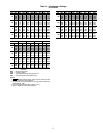
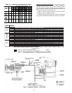
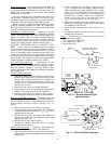
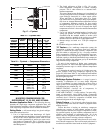
PNEUMATIC COMPENSATION OF COMPRESSOR
CAPACITY CONTROL — Adding a control air line to the
external pneumatic control connection permits pneumatic
resetting of the control point in accordance with changes in
operating conditions. Each pound of change in air pressure
resets the control one pound in the same direction. Thus, a one-
pound rise in air pressure will cause unloading to begin at a
suction pressure one pound higher than the original control
point, etc. Figure 9 shows a typical pneumatic control arrange-
ment. All components and installation instructions are field
supplied.
Fig. 8 — Capacity Control — 5H120, 5H126
CONTROL
AIR
SENSING
BULB
3 TO 15 PSI
SIGNAL TO
COMPRESSOR
PNEUMATIC CONTROLLER
OUTPUT TO INCREASE ON
DECREASE IN CONTROLLED
TEMPERATURE
Fig. 9 — Pneumatic Compensation