


27
The variety of systems using 5F,H compressors make it
impractical to cover all aspects of hot gas bypass operation.
The following guidelines will aid in determining the proper
application.
The hot gas bypass valve is basically a pressure regulating
valve installed to hold a constant compressor suction pressure.
It should operate over as small a pressure range as possible.
The normal set point of the valve should be coordinated with
cylinder unloaders so that the bypass valve starts to open at a
pressure where the last cylinder bank unloads, and is fully open
at a slightly lower pressure. Types, ratings and published appli-
cation guides for various available valves must be evaluated to
determine the proper valve and installation practice for each
application.
If a compressor system is to operate down to zero load, the
valve capacity should equal compressor capacity when fully
unloaded. For systems using multiple evaporators, it may be
necessary to use multiple hot gas valves.
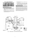
Hot gas should be taken from a point as close as possible to
compressor discharge and fed through a hot gas solenoid valve
and then through a hot gas valve. The hot gas solenoid valve
can be controlled by a pressure switch or temperature switch.
On compressors equipped with an electrically actuated cylinder
unloader, the hot gas solenoid should be wired in parallel with
the solenoid that unloads the final cylinder bank so that bypass-
ing starts immediately when all cylinders are unloaded.
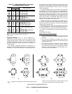
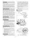
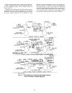
HOT GAS INJECTION INTO LIQUID LINE — When
amount of bypass is small and the evaporator has a low pres-
sure drop distribution system and existing system piping does
not present problems, hot gas is frequently injected into the
liquid line between the thermostatic expansion valve (TXV)
and the evaporator. The ideal point for hot gas injection is into
the side inlet of a side connection distributor, where inlet is
downstream of distributor orifice. If too much hot gas is
injected upstream of a distributor orifice, gas binding and
erratic expansion valve operation will result. Injection into
liquid line is recommended whenever practical, since agitation
in the evaporator and normal operation of the TXV will tend to
thoroughly desuperheat injected hot gas and prevent compres-
sor overheating.
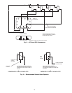
HOT GAS INJECTION INTO COMPRESSOR SUCTION —
Hot gas injection into compressor suction is sometimes neces-
sary but must be done with caution to ensure sufficient
desuperheating of hot gas and to prevent liquid slugging in the
compressor. Following guidelines should be observed:
1. Inject hot gas as close as possible to the evaporator outlet.
2. Install a TXV bulb at least 3 or 4 ft (further if possible)
downstream from the hot gas injection point to ensure
good gas mixing before the bulb.
3. Install a separate small TXV to inject liquid refrigerant
into the suction line along with bypass gas. This valve
should have capacity approximately 25% of hot gas
valve capacity since hot gas must be superheated but not
condensed.
4. Install a suction (knockout) drum in the suction line
immediately before the compressor and downstream of
the hot gas inlet and liquid injection inlet. Only larger
industrial systems or systems with many remote evapora-
tors can normally justify the extra expense of injecting
hot gas into the compressor suction.
Motor Selection Data —
Motor selection data based on
brake horsepower occurring at design operating condition is
usually satisfactory for applications in air conditioning suction
temperature range.
Required compressor starting torque is dependent on dis-
charge pressure as well as pressure differential occurring
during start-up and is the same for any compressor speed.
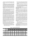
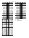
Values shown in Table 19 indicate maximum starting torque
for R-12, R-134a, R-22, R-502, and R-507/404A. In most
cases, a standard torque motor can be selected because of
the partially unloaded starting feature of the 5F and 5H
compressors.
In selection of a motor, the required motor starting torque
must exceed the compressor starting torque only when the
compressor is operating at same speed as the motor. If com-
pressor speed is less than motor speed, as on some belt drive
units, the motor starting torque requirements are reduced in
proportion to the speed ratio between the compressor and
motor because of mechanical advantage available to the motor.
In special applications or systems where there is a large
pulldown requirement, the bhp requirement during pulldown
may significantly exceed bhp at design conditions. The motor
must not be overloaded during pulldown operation. If the
motor is sized for pulldown, it will be only partially loaded
during design operation and will run inefficiently. Therefore,
select a motor that will be optimized for system design require-
ments and not for pulldown requirements. Two ways for
handling this are:
1. Install a crankcase pressure regulator in the system to
maintain a given saturated suction temperature, thereby
controlling bhp requirement, or
2. Install a current sensing device so that the motor current
draw does not exceed the maximum rated motor current.
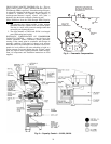
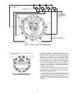
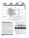
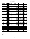
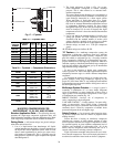
Drive Packages —
Table 20 indicates drive package
components for 5F,H standard belt drive packages. Figure 17
and Tables 21 and 22 indicate data for the flywheel used in
each of these packages.
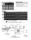
Table 19 — Compressor Starting Torques
COMPRESSOR
SIZE
%
UNLOADING
DURING
STARTING
SATURATED DISCHARGE TEMPERATURE (F)
80 F 100 F 120 F
R-12,
R-134a
R-22
R-502,
R-507/404A
R-12,
R-134a
R-22
R-502,
R-507/404A
R-12,
R-134a
R-22
R-502,
R-507/404A
Maximum Starting Torque (lb-ft)
5F20
None 19 30 32 27 42 45 34 53 57
5F30
None 22 34 37 30 47 50 39 61 65
5F40
75 18 28 30 25 39 42 32 50 53
5F60
66
2
/
3
22 34 37 30 47 50 39 61 65
5H40
75 42 65 70 57 89 95 74 115 123
5H46
75 53 81 87 71 111 119 92 144 154
5H60
66
2
/
3
51 79 85 69 107 115 90 140 149
5H66
66
2
/
3
64 99 106 86 134 144 113 175 186
5H80
75 58 90 96 79 123 130 102 158 169
5H86
75 73 113 120 99 154 162 127 197 212
5H120
66
2
/
3
91 141 151 123 191 204 160 249 266
5H126
66
2
/
3
114 176 189 154 239 255 200 311 332