


3
During compressor shutdown, gravity, thermal action and
refrigerant absorption can result in a refrigerant and oil mixture
in compressor crankcase. Gravity flow can be prevented by the
use of recommended loops, but thermal action and the absorp-
tion of refrigerant by lubricating oil cannot be prevented by
piping design.
For the above reasons, the compressor must be controlled
during idle times by one of the following methods.
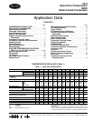
MINIMUM PROTECTION — The minimum protection that
Carrier will allow is shown in Fig. 1. Actuated control thermo-
stat energizes crankcase heater and closes the liquid line
solenoid valve simultaneously. With crankcase heaters
energized, the crankcase temperature is always held above
shutdown temperature in the evaporator coil and there will be
no refrigerant migration to the crankcase.
With this type of control, a control relay is required and
crankcase heaters have to be energized when the compressor is
not operating.
The control relay coil is located in parallel with the liquid
line solenoid, and a normally open control relay contact is
added in series with the compressor starter and other auxiliary
safety devices.
When the thermostat calls for cooling, the solenoid valve
opens and control relay is energized. This closes the relay
contact and, if other safety devices are in their normal position,
compressor will start. Simultaneously, the normally closed
compressor auxiliary contact will open, removing crankcase
heaters from the circuit.
When the thermostat is satisfied, the solenoid will close and
control relay is deenergized. This opens relay contacts and
compressor stops. This causes compressor auxiliary contacts to
close, energizing crankcase heaters.
Specifications are sometimes written to call for a degree of
protection greater than that afforded by the standard method. If
this is the case, either single pumpout or automatic pumpdown
control may be required.
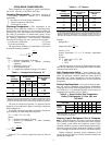
AUTOMATIC PUMPDOWN CONTROL (Fig. 2) — Pump-
down control is the most effective means of compressor control
in keeping liquid refrigerant out of the crankcase on system
shutdown.
In the basic pumpdown control sequence, the thermostat
controls the liquid line solenoid valve to stop or start the flow
of refrigerant to the evaporator as required.
The pumpdown control system permits compressor cycling
if a system malfunction allows low side pressure to rise.
Although this cycling is sometimes considered objectionable, it
illustrates need for maintenance attention and provides positive
protection against liquid refrigerant accumulating in the
compressor crankcase.
Do not use pumpdown control with dry expansion coolers
as it may cause frost pinching or freeze-up. Do not use
pumpdown control with dry expansion coolers if it is antici-
pated that there will be short bursts of system operation, as this
will result in a gradual loss of oil.
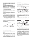
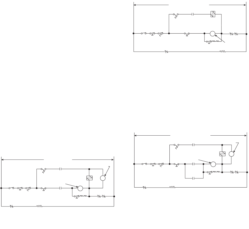
SINGLE PUMPOUT CONTROL (Fig. 3) — Pumpout con-
trol is not as effective as pumpdown control in keeping liquid
refrigerant out of the crankcase. However, it is usually satisfac-
tory when used with crankcase heaters if pumpdown is not
acceptable.
Single pumpout control is similar to pumpdown control,
except that a pumpout relay is added, a normally open com-
pressor auxiliary contact is necessary, and energizing of crank-
case heaters is required at end of each operating cycle.
With single pumpout control, when the thermostat is satis-
fied, the compressor pumps down once and stops. It starts
again only when the thermostat calls for cooling. In pumpdown
control, the compressor cycles only on the low-pressure switch,
regardless of thermostat demands.
Do not use pumpout control with dry expansion coolers as it
may cause frost pinching or freeze-up.
MANUAL PUMPDOWN — The compressor may be con-
trolled manually without the use of pumpdown, or single
pumpout control, and without crankcase heaters, provided the
system is at all times under control of a qualified operator. The
operator will pump down the system by use of manual valves
and will keep liquid, suction and discharge valves closed when
the machine is not operating.
HIGH-
PRESS.
SWITCH
AUTO-
OFF
SWITCH
OIL
FAILURE
SWITCH
LOW-
PRESS.
SWITCH
CONTROL
RELAY
COMPR
STARTER
THERMO
EVAP
AUX CONT
SOLENOID
VALVE
OIL FAILURE
SWITCH
OVERLOADS
CONTROL
RELAY
CONTROL POWER
COMPR
AUX CONT
CRANKCASE
HEATERS
Fig. 1 — Minimum Protection
HIGH-
PRESS.
SWITCH
AUTO-
OFF
SWITCH
OIL
FAILURE
SWITCH
LOW-
PRESS.
SWITCH
COMPR
STARTER
THERMO
EVAP
AUX
CONT
SOLENOID
VALVE
OIL FAILURE
SWITCH
OVERLOADS
CONTROL POWER CIRCUIT
COMPR
AUX CONT
CRANKCASE
HEATERS
Fig. 2 — Automatic Pumpdown Control
HIGH-
PRESS.
SWITCH
AUTO-
OFF
SWITCH
OIL
FAILURE
SWITCH
LOW-
PRESS.
SWITCH
COMPR
STARTER
THERMO
EVAP
AUX CONT
SOLENOID
VALVE
OIL FAILURE
SWITCH
OVERLOADS
CONTROL POWER CIRCUIT
COMPR
AUX CONT
CRANKCASE
HEATERS
PUMPOUT
RELAY CONTACT
COMP
AUX
CONTACT
PUMPOUT
RELAY
COIL
Fig. 3 — Single Pumpout Control