


19
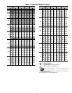
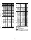
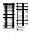
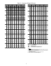
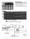
Table 15 — Weight Distribution, Compressor
Units (See drawing, Table 14)
LEGEND
NEMA — National Electrical Manufacturers Association
*Oversize frame.
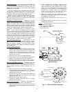
Capacity Control —
For all 5F,H compressors, a
pressure-type cylinder unloader is used. On 5F20 and 5F30
compressors, the capacity control valve is external and on 5F40
through 5H126 compressors the valve is located internally. On
all 5F,H compressors, capacity reduction is in response to
suction pressure.
The cylinder unloading mechanism is powered by a
compressor force-feed lubricating system. This feature assures
unloading of all controlled cylinders at starting regardless of
the position of the capacity control valve, since suction valves
will be held in open position until the lubricating oil pressure
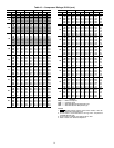
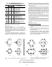
reaches its normal operating level. Refer to Fig. 4 for cylinder
unloading sequence.
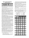
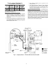
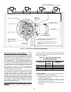
An external adjusting stem is provided to set control point
and maintain desired suction pressure. The control point is
adjustable from 0 to 85 psig suction pressure. Differential over
the complete range at any temperature level is 10.7 psig with
Refrigerant 22 and Refrigerant 502. A 7-lb spring (for use on
5F40 and larger units) is furnished with the compressor which,
when used, results in an adjustable control point from 0 to
50 psig with a 6.8 psig range. Insert a spring in the capacity
control valve when R-12 is used. See Fig. 5.
With this arrangement, suction pressure will not drop below
the control set point minus the differential within range of
capacity steps since the compressor will unload to balance its
capacity with evaporator load.
Power elements and valve lifting mechanisms are identical
on all 5F,H compressors. However, when using capacity con-
trol, various methods are used to activate the power elements.
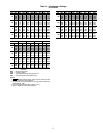
See Table 16 for unloading steps and power requirements at
each step.
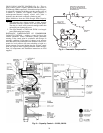
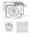
5F20 AND 5F30 (Fig. 6)
Major Elements of Control Systems:
1. Capacity Control Valve: Function is to raise or lower oil
pressure from oil pump in response to refrigerant suction
pressure.
2. Power Elements: Function is to supply power necessary
to operate valve lifting mechanism. It is modulated by the
capacity control valve.
3. Valve Lifting Mechanism: Consists of a sleeve and push
pin assembly around each controlled cylinder, designed
to hold the suction valve open, or to permit the valve to
remain in a normal operating position depending on its
actuation by the power element.
COMPR
WT DISTR (lb)
NEMA FRAME SIZE
A or D B or C
Belt Drive
5F20 115 100 182T, 184T, 213T, 215T
5F30 140 118 184T, 213T, 215T, 254T
5F30* 168 145 184T, 213T, 215T, 254T
5F40 228 165 213T, 215T, 254T, 256T
5F60 280 210 215T, 254T, 256T, 284T
5H40 410 305 256T, 284T, 286T, 324T, 326T
5H60 515 395 286T, 324T, 326T
5H60* 630 533 324T, 326T, 364T, 365T
5H80 685 558 324T, 326T, 364T, 365T, 404T
5H120 1050 728 364T, 365T, 404T
Direct Drive
5F40 210 145 213T, 215T, 254T, 256T
5F60 245 185 215T, 254T, 256T, 284T, 286T
5F60* 290 255 256T, 284T, 286T
5H40 380 275 256T, 284T, 286T, 324TS, 326TS
5H46 380 275 324TS, 326TS, 364TS, 365TS
5H80 480 360 286T, 324TS, 326TS, 364TS
5H60 480 360 365TS, 404TS
5H66 480 360
286T, 324TS, 326TS, 364TS, 365TS,
404TS
5H80 690 605 324TS, 326TS, 364TS, 365TS, 404TS
5H86 690 605 365TS, 404TS, 405TS
5H120 890 690 364TS, 365TS, 404TS, 405TS, 444TS
5H126 890 690 405TS, 444TS, 445TS
2
1
4
3
2
1
3
4
3
3
2
2
2
2
1
1
3
3
4
4
2
1
4
3
1
3
2
1
2
1
5F30
5F20
5F40
5F60
5H80, 86
5H120, 126
5H40, 46
5H60, 66
A
B
1
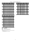
—
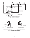
Cylinders recommended for permanently unloaded operation.
NOTE: The numerals indicate the unloading sequence and
the number of cylinders that unload with each step.
SHORT-STROKE COMPRESSORS ONLY
Fig. 4 — Cylinder Unloading Sequence