


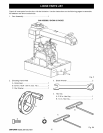
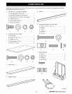
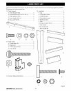
Assemblyisbestdoneintheareawherethesawwill
beused.Whenyouremovethesawandhardware
fromthepackingmaterials,carefullychecktheitems
withtheLoosePartslist.Ifyouareunsureaboutthe
descriptionof anypart,refertotheirillustrations.For
yourconvenience,allfastenershavebeendrawn
actualsize.Ifanypartsaremissing,delayassembling
untilyouhaveobtainedthemissingpart(s).
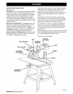
Yourradialarmsawiscapableofawidevarietyof
operations,andthusrequiresanumberof initialsetup
adjustments.However,oncethesawissetup,you
cancheckyoursawinabouttenminutesandcorrect
anymisalignmentwiththeproceduresintheAdjust-
ment section.
_ CAUTION: Perform all the procedures in both
the Assembly and Adjustments sections before
using the saw. Run a check on your saw
frequently, referring to the Adjustments section.
Failure to perform the adjustments in the initial
set up or on a frequent basis can result in poor
performance or machine damage.
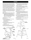
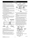
ASSEMBLING LEG STAND
See Figures 9A - 9C.
• Take the following hardware from the hardware
bags in the leg stand carton:
40 truss head screws (1/4-20 x 5/8 in.)
40 star washers (1/4 in.)
40 hex nuts (1/4-20)
• Take the following hardware from the remaining
hardware bags in the leg stand carton:
4 leveling feet
8 large hex nuts (3/8-16)
• Obtain four legs and eight braces from the leg
stand carton. See the Loose Parts section.
SHORT
IPPERBRACE
SHORT
LOWERBRACE
STAR
WASHER
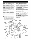
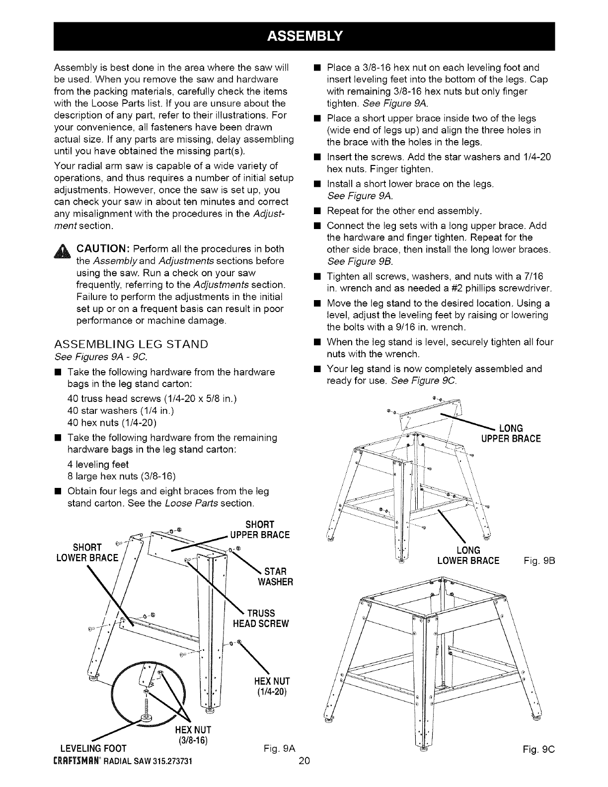
• Place a 3/8-16 hex nut on each leveling foot and
insert leveling feet into the bottom of the legs. Cap
with remaining 3/8-16 hex nuts but only finger
tighten. See Figure 9A.
• Place a short upper brace inside two of the legs
(wide end of legs up) and align the three holes in
the brace with the holes in the legs.
• Insert the screws. Add the star washers and 1/4-20
hex nuts. Finger tighten.
• Install a short lower brace on the legs.
See Figure 9A.
• Repeat for the other end assembly.
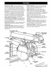
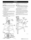
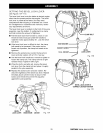
• Connect the leg sets with a long upper brace. Add
the hardware and finger tighten. Repeat for the
other side brace, then install the long lower braces.
See Figure 9B.
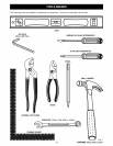
• Tighten all screws, washers, and nuts with a 7/16
in. wrench and as needed a #2 phillips screwdriver.
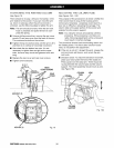
• Move the leg stand to the desired location. Using a
level, adjust the leveling feet by raising or lowering
the bolts with a 9/16 in. wrench.
• When the leg stand is level, securely tighten all four
nuts with the wrench.
• Your leg stand is now completely assembled and
ready for use. See Figure 9C.
LONG
UPPERBRACE
LONG
LOWERBRACE
Fig. 9B
TRUSS
HEABSCREW
HEXNUT
(1_-20)
HEXNUT
(3/8-16)
LEVELINGFOOT
CR_F;T=_MRN°RADIALSAW315.273731
Fig. 9A
20
Fig. 9C