


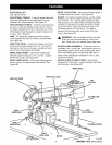
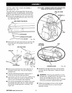
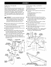
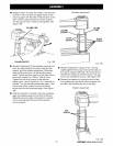

REMOVING THE BLADE
See Figure 13.
Remove the blade and blade guard assembly during
setup for safety and better access. The blade guard
includes an upper blade guard, an outer lower guard,
and an inner lower guard. The lower inner guard
consists of two overlapping slotted metal strips. The
strips are held together with a retaining screw and a
nut. Locate these items before beginning the proce-
dure.
_ WARNING: To prevent accidental contact with
the blade that could result in injury, remove the
blade and blade guard before making setups
involving the blade arbor and work stand. Use
the blade wrenches provided with your saw.
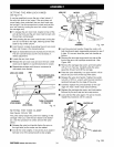
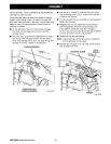
• Remove the retaining screw and nut at the bottom
of the lower inner blade guard.
• Loosen the guard clamp screw, a long thumbscrew
between the blade guard and the motor.
• Rotate and lift the guard assembly up and over the
blade, then remove it.
• Hold the blade arbor (motor shaft) with one of the
two blade wrenches provided. Put the other blade
wrench on the blade nut and turn it clockwise
(down), since the blade arbor has left hand threads.
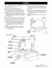
• Remove the blade nut, outer blade washer, saw
blade, and inner blade washer. Set these items
aside until all the tables have been installed and the
front table is level.
THUMBSCREW_BLADE GUARD BLADE
INNERBLADE
WASHER
BLADE TO
ROTATION TIGHTEN
BLADE
ARBOR
BLADE
i: WRENCH(2)
Fig. 13
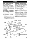
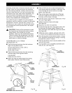
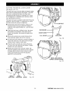
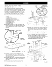
ATTACHING TABLE SUPPORTS
See Figure 14.
The table supports are a base for the three wooden
table sections and fence.
• Locate the two table supports and the following
hardware:
4 square head bolts (5/16-18 x 3/4 in.)
4 Iockwashers (5/16 in.)
4 hex nuts (5/16-18)
4 flat washers (5/16 in.)
• Attach the supports to the side of the saw base.
There are holes in both sides of each support. The
long side of each support (with the slotted holes)
fits against the saw base.
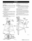
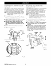
• Use two square head bolts per support, inserted
from within the saw base outward.
• Place a flat washer, a lock washer, and a hex nut
on the end of each screw.
• Position table supports so that bolts are approxi-
mately centered in slotted holes.
• Finger tighten or snug with a 1/2 in. wrench only at
this time. Final adjustments will be made later in
Leveling The Table Supports section.
TABLE FLAT
SUPPORT WASHER
SQUARE
HEADBOLT
TABLE
SUPPORT
MOUNTTABLESUPPORTS
USINGTHESEHOLELOCATIONS Fig. 14
23 CRtIFTSMRN°RADIALSAW315.273731