


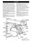
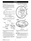
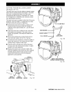
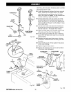
SETTING THE BEVEL LOCK LEVER
See Figures 17A -17C.
The bevel lock lever locks the blade at desired angles
other than the preset positive stop angles. The bevel
lock lever is preset at the factory but may need
readjustment after shipping or extended use. Check
for overtightness or looseness and make any neces-
sary adjustments as follows:
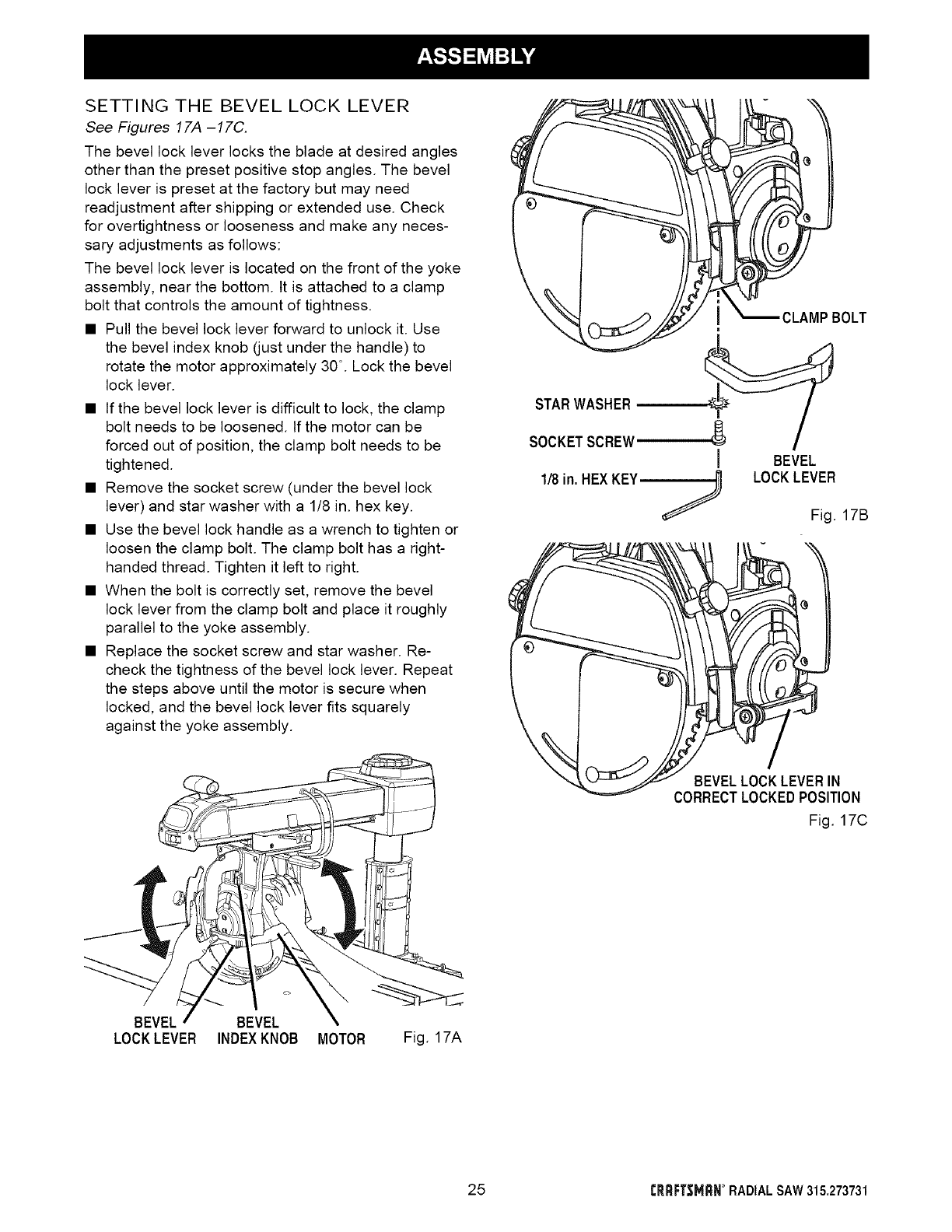
The bevel lock lever is located on the front of the yoke
assembly, near the bottom. It is attached to a clamp
bolt that controls the amount of tightness.
• Pull the bevel lock lever forward to unlock it. Use
the bevel index knob (just under the handle) to
rotate the motor approximately 30 °. Lock the bevel
lock lever.
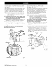
• If the bevel lock lever is difficult to lock, the clamp
bolt needs to be loosened. If the motor can be
forced out of position, the clamp bolt needs to be
tightened.
• Remove the socket screw (under the bevel lock
lever) and star washer with a 1/8 in. hex key.
• Use the bevel lock handle as a wrench to tighten or
loosen the clamp bolt. The clamp bolt has a right-
handed thread. Tighten it left to right.
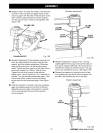
• When the bolt is correctly set, remove the bevel
lock lever from the clamp bolt and place it roughly
parallel to the yoke assembly.
• Replace the socket screw and star washer. Re-
check the tightness of the bevel lock lever. Repeat
the steps above until the motor is secure when
locked, and the bevel lock lever fits squarely
against the yoke assembly.
STARWASHER
SOCKETSCREW
1/8in.HEX KEY
CLAMPBOLT
e
I BEVEL
LOCKLEVER
Fig. 17B
BEVELLOCKLEVERIN
CORRECTLOCKEDPOSITION
Fig. 17C
BEVEL BEVEL
LOCKLEVER INDEXKNOB MOTOR Fig. 17A
25 f'RRFT,_MRN° RADIALSAW 315,273731