


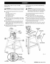
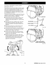
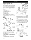
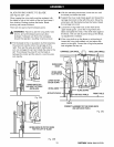

LEVELING THE TABLE SUPPORTS
See Figures 2fA and 2fB.
The table supports must be perfectly level.
• Pull the bevel lock lever forward to unlock it. Use
the bevel index knob to rotate the motor so the
arbor shaft points down. Lock the bevel lock lever.
• Release the arm lock knob to angle the arm. Begin
by positioning the arbor shaft over the back of the
highest table support. Normally this is the left side.
See Figure 21A.
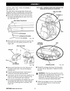
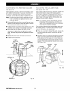
• Lock the arm lock knob and the carriage lock knob.
• Using one of the blade wrenches as a feeler gage,
place it on the table support below the arbor shaft.
• With the elevating handwheel, carefully lower the
motor until the shaft just touches the wrench. The
wrench should move with only slight resistance.
Securely tighten the back screw on the table
support.
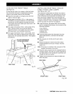
• Without changing the elevation, move the arm to
place the blade arbor over the front of table sup-
port. See Figure 21B.
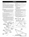
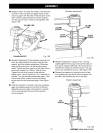
• Place the wrench below the shaft and check that
the clearance is the same. If not, adjust the table
support until it is the same. Securely tighten the
front screw.
• Move the arm to the opposite side and repeat the
above procedure. When the opposite side is level,
recheck the first side to make sure that it is still
accurate and even.
• Return the saw and motor to normal height and
position.
ARMLOCK KNOB_
BEVEL
LOCKLEVER
BLADEWRENCH
ATBACK
BLADE
ARBOR
LEFTSlDE
TABLESUPPORT
RIGHTSIDE
TABLESUPPORT
ELEVATING
HANDWHEEL
29
Fig. 21A
rRRFTSMRN°RADIALSAW315.273731