


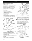
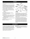

PARALLELING BLADE TO TABLE
See Figures 31A-31C.
This procedure squares the blade to the table at 90°
bevel so horizontal cuts will be accurate. This also
reduces kickback, as well as splintering and burning
of the cut edges of the workpiece. If the blade is not at
90 ° bevel, follow the steps to rotate the blade unit
slightly. You will need a framing square and a flat
blade screwdriver.
_lk WARNING: The blade must be perfectly parallel
to the table at the 90° reading on the bevel scale.
If not, kickback could result, as well as splinter-
ing or burning the cut. Kickback can result in
serious personal injury as the workpiece can be
thrown at the operator.
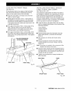
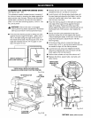
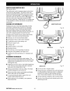
• Use the arm lock knob to lock the arm in 0° miter
position (straight forward).
• Turn the elevating handwheel to raise the blade at
least 2 in. above the table.
• Release the bevel lock lever below the handle. Use
the bevel index knob, just under the handle, to turn
the motor to 90 °. The blade will be horizontal. Lock
the bevel lock lever.
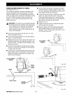
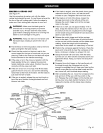
• Place the framing square with the short end hang-
ing down in front of the worktable and the long side
on edge under the blade.
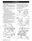
• Lower the arm with the elevating handwheel so the
blade surface rests on the square. Turn the blade
slightly if necessary so the face of the blade, not a
tooth, lies on the square.
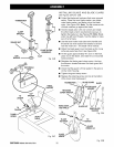
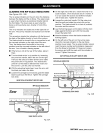
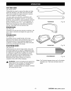
NOADJUSTMENT
NEEDED
• Check whether the blade is flat against the edge
the entire length or whether a gap is visible. If you
can see a gap, adjust the blade to be at 90° bevel
to the table with the following steps.
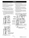
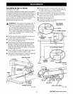
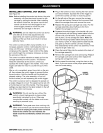
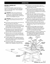
• Unlock the bevel lock lever. Loosen the rear motor
mount nut, which holds the motor on the yoke.
Place a flat blade screwdriver in one of the slots,
and rotate the cam behind the nut to eliminate the
gap between the blade and the square.
• Retighten the nut.
• Tighten the bevel lock lever. Recheck the blade
and the square for any gaps.
• Raise the blade with the elevating handwheel to
approximately halfway up. Index the blade to a
vertical 0° bevel with the bevel index knob. Lock it
with the bevel lock lever.
ADJUSTMENT GAP
NEEDED
FENCE
/
FRONTTABLE
BLADE
FRAMING_
SQUARE
BEVEL
LOCK
LEVER
Fig. 31A
CAM
Fig. 31B
Fig. 31C
rRRF'[SMRN°RADIALSAW 315.273731 38