11
RC GROUP - 149_ItEn.0102
SCHEDA "ADDR"
SCHEDA INDIRIZZAMENTO
La scheda è installata di serie sulla BOARD "A" e sull'even-
tuale BOARD "B".
La scheda "ADDR" definisce il codice di indirizzamento
necessario al microprocessore per determinare la funzio-
ne e l'eventuale posizione nella rete LAN della scheda
BOARD su cui è installata.
Tramite i Dip-switch 1÷6 è possibile impostare il codice di
indirizzamento della scheda.
I LEDs "R" "G" "V" indicano:
"R"incompatibilità hardware (luce rossa intermittente).
incompatibilità software (luce rossa).
"G"trasmissione dati in corso (luce gialla intermittente).
"V" settaggio corretto per la rete LAN (luce verde).
Il LED verde rimane acceso anche se non è prevista la
rete LAN.
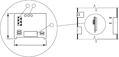
Fig. 3
1.LEDs "R" "G" "V".
2.Dip-switch per impostazione codice indirizzamento.
3.Connettore.
"ADDR" BOARD
ADDRESS BOARD
This board is standardly installed on BOARD "A" or on the
eventual BOARD "B".
The "ADDR" board allows to fix the address code neces-
sary to the microprocessor to determine the function and
the eventual position in the LAN network of the BOARD on
which it is installed.
Through the Dip-switch 1
÷
6 it is possible to set the board
address code.
The "R" "G" "V" LEDs show:
"R"hardware not compatible (blinking red light).
software not compatible (red light).
"G"data transmission (blinking yellow light).
"V" correct set for the LAN network (green light).
The green LED keeps lighting even if the LAN network
is not foreseen.
1."R" "G" "V" LEDs.
2.Dip-switch for address setting.
3.Connector.
R
off
6
1
GV
2
1
3
1
J20
J2
J15
J19
J14
50
39
MP2000 AIR CONDITIONERS
Sistema di controllo a microprocessore per condizionatori d'aria •
Air conditioners microprocessor control system


