


179
RC GROUP - 149_ItEn.0102
MP2000 AIR CONDITIONERS
Sistema di controllo a microprocessore per condizionatori d'aria •
Air conditioners microprocessor control system
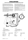
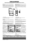
• HC1 (Heating/Cooling uscita 1): Modo di funziona-
mento uscita 1.
H = Caldo - C = Freddo
• HC2 (Heating/Cooling uscita 2): Modo di funziona-
mento uscita 2. Analogo a HC1
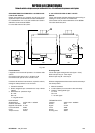
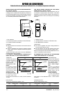
• rP1 (Relè protection 1). Stabilisce la posizione del relè
1 in caso di sonda guasta.
ro =relè aperto - rc =relè chiuso.
• rP2 (Relè protection 2). Stabilisce la posizione del relè
2 in caso di sonda guasta. Analogo a rP1
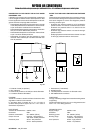
• LF1 (LED Function 1). Indica se il LED 1 deve essere
acceso o spento in corrispondenza all'uscita 1 attiva.
di =diretta = LED acceso per uscita attiva
in =inversa = LED spento per uscita attiva
• LF2 (LED Function 2). Indica se il LED 2 deve essere
acceso o spento in corrispondenza all'uscita 2 attiva.
Analogo a LF1.
• dP (decimal point). Permette di avere la visualizzazione
con o senza punto decimale.
oF =senza punto decimale - on = con punto decimale
• hdd (half digit display). Permette di selezionare sulla
cifra più a destra del display la visualizzazione normale
(hdd =n) o delle sole cifre 0 e 5 (y) - risoluzione di 0,5°C.
• tAb (tAbella parametri). Indice di configurazione para-
metri settati in fabbrica; non modificabili dall'utente.
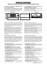
Fig.114
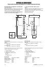
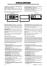
SEGNALAZIONE ERRORE
Il controllo visualizza due tipi di errore:
- - - nel caso di sonda in corto circuito.
EEE nel caso di sonda interrotta, non collegata e valori di
temperatura fuori range.
L'uscita su relè è libera da tensione ed indipendente.
Non superare la corrente massima (6A/250 Vac/AC1).
Con carichi superiori usare un contattore di adatta potenza.
DATI TECNICI
Alimentazione 24Vac/dc ±15% - 50/60Hz - 3VA
Portata contatto relè 6A - 250Vac - AC1
Potere di commutazione 1000VA (Vac) - 50W (Vdc)
• HC1 (Heating/Cooling output 1): Relay switch function
output 1.
H = Heating - C = Cooling
• HC2 (Heating/Cooling output 2): Relay switch function
output 2. Same as HC1
• rP1 (Relay protection 1). Determines the status of the
relay 1 in case of sensor defect.
ro =relay open - rc =relay closed
• rP2 (Relay protection 2). Determines the status of the
relay 2 in case of sensor defect. Same as rP1
• LF1 (LED Function 1). Determines whether the status
light is ON or OFF in relation to output 1.
di =direct= light on when output 1 is energized
in =reverse= light off when output 1 is energized
• LF2 (LED Function 2). Determines whether the status
light is ON or OFF in relation to output 2.
Same as LF1.
• dP (decimal point). Choose whether the resolution is
required with or without decimal point.
oF =Without decimal point - on = With decimal point
• hdd (half digit display). The right-most digit can be set
to read-out in 0 or 5 only, or in all 10 digits.
• tAb (tAble of parameters). This shows the configura-
tion of the parameters as set in the factory; can not be
modified.
ERROR SIGNALLING
The device display two type of error:
- - - in case of sensor in short-circuit.
EEE in case of sensor break, sensor absence or tempera-
ture values out of range.
The relay output contact is voltage free and independent.
Do not exceed the resistive rating of 6A/250Vac/AC1.
For larger loads, please use an external contactor or relay.
TECHNICAL DATA
Feeding 24Vac/dc
±
15% - 50/60Hz - 3VA
Relay resistive rating 6A - 250Vac - AC1
Commutation cap. 1000VA (Vac) - 50W (Vdc)
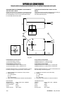
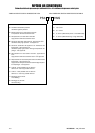
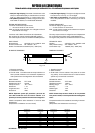
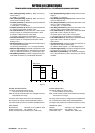
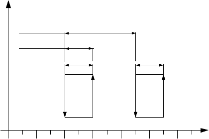
OFF
OFF
ON
ON
III
Set point 2
Set point 1
d1 d2
(°C)