


RC GROUP - 149_ItEn.0102
26
J3
T1
T2
B8
G0
B7
G
G0
O1
O2
C1
C2
L1
L2
J2
J1
J6
J5
J4
1
J17
230/400V
24V
24V
1
1
1
J20
J22
1
J24
1
J6
1
J5
1
J4
1
J3
1
J2
1
J1
RS485
J15
J29
J9 J8
J21
J19
G
G0
J11
GND
RX/TX-
RX/TX+
ID11-230Vac
ID11-24Vac
ID11-R
-----------
ID12-R
ID12-24Vac
ID12-230Vac
NO8
C8
------
NO7
C7
------
NO6
C6
------
NO13
C13
C3
NO3
------
C4
NO4
------
C5
NO5
------
C12
NO12
C1
NO1
------
C2
NO2
IDCM1
ID5
ID4
ID3
ID2
ID1
IDCM2
ID10
ID9
ID8
ID7
ID6
B6
AVSS
B5
B4
AVSS
B3
B2
AVSS
B1
B8
+24Vdc
B7
NO11
C11
NC11
------
NO10
C10
NC10
------
NO9
C9
NC9
VG0
VG1
Y1
Y0
321
J14
321
3
2
1
3
2
1
3
2
1
J28
J14 = 2-3
J28 = 2-3
J29 = 2-3
3
2
1
K11
FUSE
K10
K9
K8
K7
K6
K13
K3
K2
K1
K4
K5
K12
+ (G)
NTC (°C)
NTC (°C)
H (%rH)
M
9
8
10
10
11
11
1
6
2
7
3
4 5
9
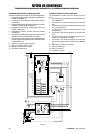
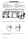
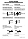
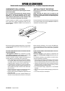
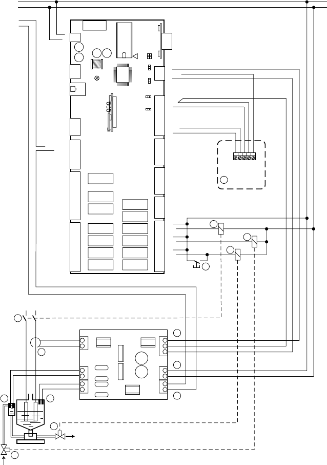
MP2000 AIR CONDITIONERS
Sistema di controllo a microprocessore per condizionatori d'aria •
Air conditioners microprocessor control system
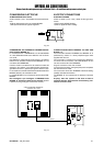
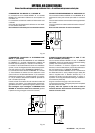
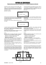
HUMIDIFICATION SYSTEM CONNECTION
The humidification system needs the following connec-
tions:
1 Connection of the combined temperature/humidity sen-
sor to BOARD "A".
2 Connection of the electric feeding for the humidifier
card.
3 Connection of the humidifier amperometric transformer
to the humidifier card.
4 Connection of the water conductivity sensor to the
humidifier card.
5 Connection of the water level sensor to the humidifier
card.
6 Connection of the water level digital output from hu-
midifier card to BOARD "A" (24Vac).
7 Connection of the water conductivity and humidifier
current analog outputs from humidifier card to BOARD
"A".
8 Push button for manual water drain
9 Relay for water drain
10 Relay for water fill
11 Humidifier contactor
CONNESSIONE SISTEMA DI UMIDIFICAZIONE
Il sistema di umidificazione prevede i seguenti collegamenti:
1 Collegamento della sonda combinata di temperatura/
umidità alla BOARD "A".
2 Collegamento alimentazione elettrica della scheda
umidificatore.
3 Collegamento trasformatore amperometrico di corrente
umidificatore alla scheda umidificatore.
4 Collegamento sensore di conducibilità acqua alla
scheda umidificatore.
5 Collegamento sensore di livello acqua alla scheda
umidificatore.
6 Collegamento uscita digitale livello acqua dalla scheda
umidificatore alla scheda BOARD "A" (24Vac).
7 Collegamento uscite analogiche di conducibilità acqua
e corrente umidificatore dalla scheda umidificatore alla
scheda BOARD "A".
8 Pulsante per scarico acqua manuale.
9 Relè per comando scarico acqua.
10 Relè per comando carico acqua.
11 Teleruttore umidificatore.
Fig. 26