RC GROUP - 149_ItEn.0102
28
MP2000 AIR CONDITIONERS
Sistema di controllo a microprocessore per condizionatori d'aria •
Air conditioners microprocessor control system
COLLEGAMENTO PER SISTEMA DI COMPENSAZIO-
NE SET POINT TEMPERATURA
La connessione è a cura del Cliente; utilizzare un cavo
schermato ad 1 coppia intrecciata con sezione di 0,5 mm
2
(tipo AWG20).
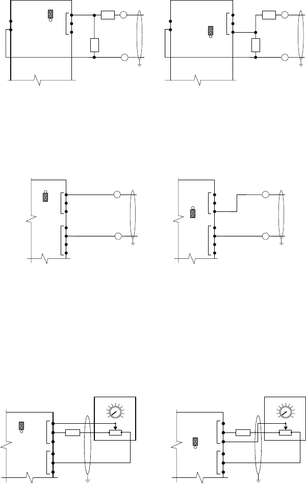
Collegamento per sistema di compensazione set point
temperatura automatico (segnale in tensione).
Il segnale di compensazione proviene da un sistema ester-
no (sonde attive o sistema di supervisione) e può essere
collegato a più unità contemporaneamente.
In base al segnale installare le resistenze da 0,5÷1W, non
fornite, come indicato in figura e predisporre il ponticello
J28 per l'ingresso B7 o il ponticello J29 per l'ingresso B8.
Segnale R1 R2
0
÷1V -- --
0÷5V 330Ω 1300Ω
0
÷10V 330Ω 3000Ω
0÷20V 330Ω 6200Ω
Fig. 29
Collegamento per sistema di compensazione set point
temperatura automatico (segnale in corrente).
Il segnale di compensazione proviene da un sistema ester-
no (sonde attive o sistema di supervisione) e può essere
collegato ad una sola unità.
Fig. 29a
Collegamento per sistema di compensazione set point
temperatura manuale.
Vengono utilizzati un potenziometro da 1KOhm ed una
resistenza da 23KOhm collegati come indicato.
Predisporre il ponticello J28 per l'ingresso B7 o il ponticello
J29 per l'ingresso B8 su 2-3 per segnale in tensione.
Il sistema prevede il collegamento di un potenziometro per
ogni unità.
Fig. 30
Separare quanto più possibile i cavi dei segnali dai
cavi dei carichi induttivi e di potenza per evitare possi-
bili disturbi elettromagnetici.
RC GROUP declina ogni responsabilità per una non
corretta esecuzione del collegamento.
BOARD
J1
J29
B8
G
G0
G
G0
0÷1V
0÷5V
0÷10V
0÷20V
R1
R2
3
2
1
+
0÷1V
0÷5V
0÷10V
0÷20V
–
B7
–
R1
R2
+
BOARD
J1
J28
3
2
1
BOARD
J1
B8 (0÷1V)
AVSS
23KΩ 23KΩ
+V
J2
1KΩ
3
1
2
22
27
23
24
25
26
1KΩ
3
1
BOARD
J1
B7 (0÷1V)
AVSS
+V
J2
2
22
27
23
24
25
26
J29
3
2
1
J28
3
2
1
CONNECTION OF THE TEMPERATURE SET POINT
COMPENSATION SYSTEM
Connection is by Customer care.
For this connection please use a single twisted-pair shielded
cable with section of 0,5mm
2
(type AWG20).
Connection for automatic temperature set point com-
pensation (voltage signal).
The compensation signal coming from an external system
(active sensor or supervision system) and it is possible a
multipoint connection with more units.
According to the signal type install two 0,5
÷
1W resistances,
not furnished, as shown in the picture and predisposition of
the J28 jumper, for inlet B7, or J29 jumper for inlet B8.
Signal R1 R2
0
÷
1V -- --
0
÷
5V 330
Ω
1300
Ω
0
÷
10V 330
Ω
3000
Ω
0
÷
20V 330
Ω
6200
Ω
Connection for automatic temperature set point com-
pensation (current signal).
The compensation signal coming from an external system
(active sensor or supervision system) and it is possible a
single connection with one units.
Connection for manual temperature set point compen-
sation.
Connect a remote 1KOhm potentiometer and a 23Kohm
resistance as per following wiring diagram.
Set the J28 jumper, for inlet B7, or J29 jumper for inlet B8
on 2-3 for voltage signal.
The system provides the connection of one potentimeter
for each unit.
Separate as much as possible the signal cables from
the inductive load and power cables, to avoid any
electromagnetic noise.
RC GROUP is not responsible for any wrong connec-
tion.
BOARD
J1
J29
B8
AVSS
0÷20mA
J2
3
2
1
+
0÷20mA
–
B7
AVSS
J2
–
+
BOARD
J1
J28
3
2
1


