155
RC GROUP - 149_ItEn.0102
MP2000 AIR CONDITIONERS
Sistema di controllo a microprocessore per condizionatori d'aria •
Air conditioners microprocessor control system
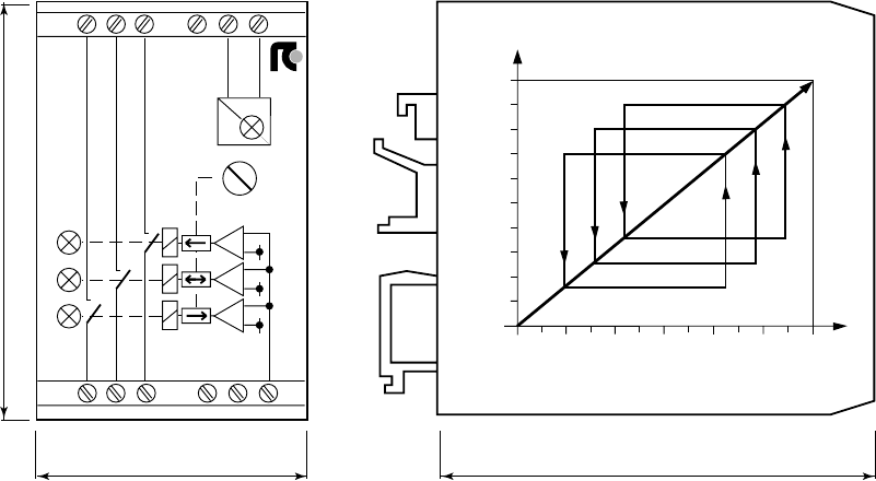
CONVERTITORE DI SEGNALE A 3 STADI - RC470
Il dispositivo è posizionato all'interno del quadro elettrico e
trova la sua principale applicazione per trasformare un
segnale di tensione (0÷10Vdc) in 3 stadi di uscita
sequenziali ON-OFF, liberi da tensione.
Fig. 89
FUNZIONI
I relè intervengono ad una tensione prestabilita semplifi-
cando così le modalità di taratura manuale che risultano
essere difficoltose ed imprecise.
La logica di funzionamento prevede che primo relè si attivi
con un segnale proporzionale proveniente dal micropro-
cessore di 7Vdc, il secondo relè a 8Vdc ed il terzo a 9Vdc.
L'intervento dei relè 2 e 3 è ritardato di un valore temporale
impostato tramite il potenziometro "DELAY" per un periodo
compreso tra 3 e 7 secondi.
Se, durante il periodo di temporizzazione, il segnale pro-
porzionale torna al di sotto della soglia del rispettivo relè, il
temporizzatore si ripristina non attivando il relè.
Con un segnale proporzionale ≥ 9Vdc tutti i relè sono
attivati in sequenza. Per disattivare il terzo relè occorrerà
che il segnale proporzionale scenda a 3Vdc, per il secondo
a 2Vdc e per il primo a 1Vdc.
Per la disattivazione dei relè 1 e 2 l'apparecchio temporizza
l'intervento con un valore temporale inversamente propor-
zionale al settaggio effettuato.
Sono presenti LED per segnalazione presenza tensione
(verde) ed intervento di ogni relè (rosso).
Esempio:
DELAY 3s: Attivazione relè dopo 3 secondi
Disattivazione relè dopo 7 secondi
DELAY 7s: Attivazione relè dopo 7 secondi
Disattivazione relè dopo 3 secondi
DATI TECNICI
Alimentazione 24Vac ± 15% - 50/60Hz - 1VA
Potenza commutabile 5A - 250Vac - 1000VA - AC1
Isolamento 2kV (RMS)
Ingresso segnale 1 ÷ 10 Vdc
Ritardo 3 ÷ 7 secondi
3-STAGES SIGNAL CONVERTER - RC470
The device is placed in the electric box and it has been
designed to transform a 0
÷
10Vdc proportional signal in 3
sequential ON-OFF stage volt free.
FUNCTIONS
The relays activates at a pre-scheduled voltage in order to
simplify manual settings otherwise complicate and impre-
cise.
The system logic is designed to activate first relay with a
7Vdc proportional signal, the second with a 8Vdc signal
and the third with a 9Vdc one.
The intervention of second and third relays is delayed of a
time adjustable between 3 and 7 seconds through the
"DELAY" potentiometer.
If during the set period of delay, the signal fall back below
respective threshold, the timer is reset to zero and the relay
is not activated.
With a proportional signal
≥
9Vdc all relays are activated in
sequence. To obtain the deactivation of third relay the
signal will have to drop to 3Vdc, while to deactivate the
second to 2Vdc and the first to 1Vdc.
To deactivate relays 1 and 2 the device is delaying the
intervention at a time proportional to the set value.
A green LED to indicate voltage presence is installed on the
device and every relay is having a red LED to signal
activated mode.
Example:
DELAY 3s: Relay activated after 3 seconds
Relay deactivated after 7 seconds
DELAY 7s: Relay activated after 7 seconds
Relay deactivated after 3 seconds
TECHNICAL DATA
Feeding 24Vac
±
15% - 50/60Hz - 1VA
Switching power 5A - 250Vac - 1000VA - AC1
Insulation 2kV (RMS)
Signal input 1
÷
10 Vdc
Delay 3
÷
7 seconds
4
SIGNAL CONVERTER RC470
7s
3
24Vac
~
~
=
1
4
6
0V
DELAY
-
+
0..10Vdc
6
5
3
-
+
2
-
+
1
789
23
5
1
1
2
3
4
5
6
7
8
9
10
2
3
1
2
3
V
¡C
%rH
kPa
40 75
80


