


153
RC GROUP - 149_ItEn.0102
MP2000 AIR CONDITIONERS
Sistema di controllo a microprocessore per condizionatori d'aria •
Air conditioners microprocessor control system
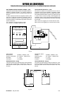
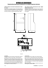
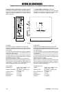
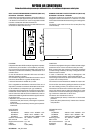
R1-R2-R3: bilanciamento fasi. Set tarato in fabbrica - non
modificare.
LED: apparecchio in
tensione.
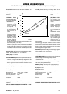
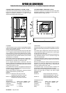
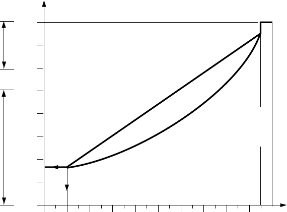
LIN/QUAD (JP9):
ponticello per definire
la risposta della tensio-
ne in uscita: LINEARE
o QUADRATICO.
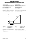
- LINEARE: Ad ogni
variazione del se-
gnale di comando
corrisponde, in
modo proporziona-
le, una variazione
della tensione di
uscita.
- QUADRATICO:
Consente di ottene-
re partenze più dolci
del carico. In pratica
otteniamo piccole
variazioni di veloci-
tà del ventilatore
per rilevanti variazioni della tensione di comando a valori
bassi del segnale (tra 0 e 4Vdc).
Viceversa si ottengono rilevanti variazioni di velocità del
ventilatore per piccole variazioni della tensione di co-
mando a valori alti del segnale (tra 7 e 10Vdc). Ciò offre
risposte più rapide all'avvicinarsi al limite superiore della
tensione di comando.
10V/
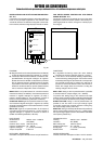
µCH (JP7): definisce la tipologia del segnale di co-
mando. Set impostato a 10V - non modificare.
INPUT (JP5): non utilizzato
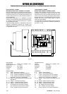
CUT-OFF/MIN (JP8): definisce il comportamento del rego-
latore quando la tensione di comando scende ad 1Vdc.
- CUT-OFF: il regolatore interrompe l'erogazione della
tensione di uscita e non alimenta più il carico.
- MIN: il regolatore imposta la tensione di uscita al valore
MIN (set di fabbrica 80V).
50Hz/60Hz (JP13): definisce la frequenza di alimentazione.
I/V (JP6): non utilizzato
DATI TECNICI
Alimentazione 400Vac ±15% - 50/60Hz
Segnale di comando 0 ÷ 10 Vdc
Grado di protezione IP20
Potenza assorbita 8VA
Impedenza 10KΩ
Tempo di salita 0,5 secondi
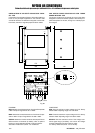
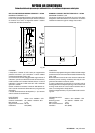
Il carico può essere collegato indifferentemente a stella o
triangolo .
IN CASO DI COLLEGAMENTO A STELLA, IL CENTRO
STELLA NON DEVE ESSERE COLLEGATO AL NEU-
TRO PER NESSUN MOTIVO.
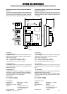
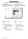
R1-R2-R3: phases balancing. It is factory setted - do not
modify.
LED: voltage pres-
ence.
LIN/QUAD (JP9):
jumper to set the out-
put voltage in LIN-
EAR or QUADRATIC
mode.
LINEAR: for each
voltage command
signal variation corre-
sponds, in propor-
tional mode, a varia-
tion of the output volt-
age.
QUADRATIC: allows
to obtain soft start of
the load. Practically,
small fan speed varia-
tions for bigger volt-
age command signal
variations are ob-
tained at lower values
(from 0 to 4Vdc).
Viceversa, bigger fan speed variations for small voltage
command signal variations are obtained at higher values
(from 7 to 10Vdc).
This allows faster reaction of the device when the voltage
command signal is at higher values.
10V/
µ
CH (JP7): fixes the voltage command signal type. It
is factory setted to 10V - do not modify.
INPUT (JP5): Not used
CUT-OFF/MIN (JP8): fixes the working mode of the device
when the voltage command signal drops to 1Vdc.
- CUT-OFF: the device cut-off the output voltage and does
not feed the load.
- MIN: the device automatically set the output voltage to
MIN value (factory setted to 80V).
50Hz/60Hz (JP13): fixes the power supply frequency.
I/V (JP6): Not used
TECHNICAL DATA
Feeding 400Vac
±
15% - 50/60Hz
Voltage command signal 0
÷
10 Vdc
Protection degree IP20
Absorbed power 8VA
Impedance 10k
Ω
Rising time 0,5 seconds.
The load can be connected in star or delta mode.
IN CASE OF STAR CONNECTION, THE STAR POINT
MUST NOT BE CONNECTED TO THE NEUTRAL.
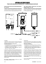
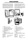
10Vdc5
V 400
350
300
250
200
MIN MAX
150
100
80
CUT-OFF
SOGLIA
JP9 - LIN
JP9 - QUAD
MIN
50
0
0
Fig. 87