


Transmitter
®
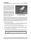
any free space between the transmitter and the
side walls of the housing. If necessary,
fabricate an “insert” behind the transmitter to
ensure a snug fit. When wrapping with tape,
be sure that the pitch will not be offset. If more
tape is on one end than the other, the trans-
mitter will not be level in the housing. Also, be
sure that metal-to-metal contact is avoided.
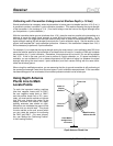
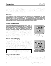
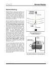
Temp Dot
Index Slot at
6 o'clock Position
Front End Cap of Transmitter
Showing Temp Dot and Index Slot
Before purchasing a new housing, place a
transmitter inside and check for a snug fit.
Also check that the index slot fits snugly over
the key in the housing. If the key is too narrow,
the transmitter can rotate and cause damage
to the index slot. There are particular “wear
patterns” that occur on transmitters that do not
fit properly in the housing. If you send a
transmitter to DCI for testing, please specify
what type of housing you are using.
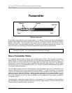
Because the transmitter’s antenna is positioned centrally (as shown on the previous page), it is important
that the windows or slots in the housing (through which the signal is emitted) are positioned to allow the
transmitter’s signal to emit with minimal restriction. The slots must number at least five and have a length
of no less than 8 inches (20 cm). These slots must be centered directly over the midpoint of the
transmitter. The width of the slots may be as narrow as necessary to maintain housing strength.
(Drawings showing the proper slot width, length, and positioning can be obtained by request from DCI.)
These slots must not have any filler material containing metal particles, e.g., liquid steel.
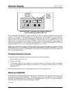
To install a transmitter in the housing:
1. Examine the transmitter to verify that there is no moisture inside the battery compartment, that the
springs inside the battery compartment have not been permanently compressed, and that the tem-
perature indicator (temp dot) located at the front end of the transmitter is not black.
2. Insert the correct number of C-cell alkaline batteries into the battery compartment with the positive
end in first. Place cap over battery compartment and tighten. (See “Batteries” below.)
3. Place the transmitter in the housing with the index slot over the anti-roll pin positioned as discussed
above in this subsection. The 12 o’clock position should correspond to the tapered or flattened sur-
face of a typical directional drill head pointed upward.
4. Verify that the transmitter is emitting the appropriate amount of signal (see Operational Tests) and
conduct other tests as discussed in the
System Operating Instructions Section before you start drilling.
NOTE: Place the transmitter in the housing and verify that pitch readings remain the same
when the housing is held level and rotated through at least four of the 12 clock
positions.
22 DigiTrak
®
Mark III Operator’s Manual