


®
DIGITAL CONTROL INCORPORATED
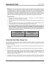
Locating
Locating Mode
458
202
22
+
~
Plus (+)
Indicator
Signal
Strength
Predicted
Depth
Transmitter
Temperature
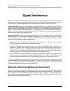
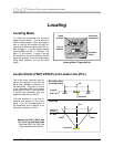
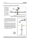
Locating Mode (Trigger Held In)
To locate the transmitter the receiver’s
trigger must be held in. This is referred to
as the “locating mode”. When the trigger is
held in, the top left window will stop dis-
playing pitch with the flashing pitch/roll up-
date squiggle (“~”) and will instead display
signal strength and the “+/–” indicator. The
plus (“+”) and minus (“–”) signs in the top
left window
are the key to locating and will
guide the operator to the tool (transmitter)
using three locations, not just the peak
signal.
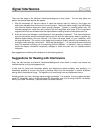
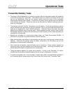
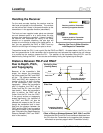
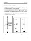
Locate Points (FNLP
& RNLP) and Locate Line (PLL)
RNLP
FNLP
Transmitter
PLL
RNLP
FNLP
Surface of
Ground
Transmitter
Bird's Eye View
(Looking Down)
Side View
Axis Line
PLL
Drill
Drill
Two of the three locations used for
guiding the operator to the tool are
points that represent extensions of
the transmitter. One point is in front
of the transmitter (the front negative
locate point or FNLP), and the other
is behind the transmitter (the rear
negative locate point or RNLP).
The third location is a line that re-
presents the position of the trans-
mitter. This line is perpendicular to
the transmitter and is referred to as
the positive locate line or PLL.
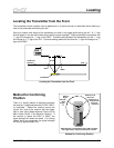
Geometry of FNLP, RNLP, and
PLL from Top and Side Views
Note how RNLP and FNLP are
equal distances from the PLL.
DigiTrak
®
Mark III Operator’s Manual 43