


Operational Tests
®
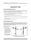
¾ Battery Life – Verify the housing slots (windows) are properly aligned over the transmitter’s antenna.
If the battery life of a transmitter seems to be shorter than that noted in the specifications provided in
the Transmitter Section, it could be due to battery arcing, which can occur in hard drilling conditions.
transmitter batteries arc when they bounce/slam into each other, losing contact intermittently. This
usually results in a permanently compressed positive contact and, therefore, no contact or signal. It
is also possible for a defective transmitter to draw more current than it should, resulting in shorter
battery life. Perform the following test to determine if a transmitter is drawing too much current.
Current Draw Test:
1. Assemble the necessary equipment for the test: Transmitter, C-cell alkaline batteries for
transmitter, housing, current/amp meter (0-500 mA).
2. Place the batteries in the transmitter (leave off the battery cap) and place the transmitter in the
housing.
3. Set the amp meter to DC amps (symbol looks like mA on the amp meter) and plug the posi-
tive (red) connector wire into the highest setting location on the meter (10 A).
4. Place the meter’s negative probe into the transmitter battery compartment making contact with
the end of the battery while placing the red probe onto the battery housing of the transmitter. It
may be necessary to roll the housing to “wake up” the transmitter. The meter displays amps, not
milli-amps, so be sure to convert by moving the decimal three places to the right (for example, a
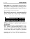
reading of 0.104 A would be 104 mA). The table below shows the target current ranges in milli-
amps for properly functioning transmitters.
Transmitter Model Average Current (mA)
DT (Yellow, Standard Range)
100 ± 20
DX (Red, Long Range)
220 ± 20
D4X (DX w/ Extended Life)
110 ± 20
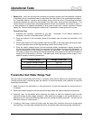
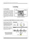
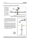
Transmitter Salt Water Range Test
This test should be performed when there is a question about salinity affecting the transmitter’s range.
The test requires rope, a measuring tape, the receiver, an active transmitter, and a platform to lower the
transmitter into the water.
1. Attach the rope to the transmitter in a “sling-like fashion” so that the transmitter will remain level as it
is lowered.
2. Secure the measuring tape to the rope so that the depth below the water surface can be observed.
3. Gradually lower the transmitter while observing the depth on both the measuring tape and the
receiver’s bottom window (trigger released). Also observe the squiggle in the top left window, is it
flashing every 2.5 seconds indicating proper pitch/roll updates are being received? This test can be
difficult to conduct in a swift current.
4. If testing in tidal areas, conduct the test under the same tidal conditions that will be encountered
during drilling. Incoming tides increase the salinity of brackish water and cause greater interference.
40 DigiTrak
®
Mark III Operator’s Manual