


®
Operational Tests
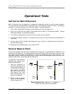
¾ Defective Transmitter – With the transmitter and receiver on, place the transmitter against the
receiver (long side of transmitter parallel to long side of receiver) while holding in the trigger. If you
see anything less than 999 in the top left window and 000 in the bottom window, it is likely that there
is a broken antenna in the transmitter. You will need a new transmitter. Readings of 999 and 000
indicate that the transmitter is sending the appropriate amount of signal when held close to the
receiver (12-20 inches [30-51 cm] for a yellow transmitter and 20-40 inches [50-100 cm] for a red
transmitter); this is called signal saturation.
NOTE: Older transmitters have an LED in the front end cap near the index slot indicating that the
batteries are loaded properly and that the transmitter is powered up.
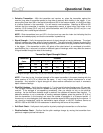
¾ Signal Strength – Verify the appropriate amount of signal strength at varying distances. The signal
strength indicates the power output of each transmitter. The signal strength is tested by placing the
receiver and transmitter (inside the housing) parallel to one another at varying distances while holding
in the trigger. If the transmitter is within ±60 points of the chart below it is considered to be within
specifications (the ± variance is to allow for different types of housings, which may affect the amount
of signal emitted through the slots of the housing).
Transmitter Signal Strength Values*
Transmitter
Distance
Color
5 ft (1.5 cm) 10 ft (3 m) 15 ft (4.5 m) 20 ft (6 m) 30 ft (9 m)
Blue 600 420
Yellow 740 560 455 380 275
Red 800 620 515 440 335
*The signal strength values may vary by up to 60 points depending on the type of housing being used.
NOTE: From day to day, the signal strength of the same transmitter in the same housing with the
same receiver at 10 ft (3 m) should be the same. If not, it may indicate interference or a bad
transmitter. Any variation in signal strength will affect receiver calibration and result in erroneous
depth/ distance readings.
¾ Pitch/Roll Updates – Verify that the squiggle (“~”) in the top left window flashes every 2.5 seconds.
This squiggle indicates that pitch/roll updates are being sent from the transmitter and heard by the
receiver. If the squiggle is not appearing consistently, then you should not rely on the pitch/roll
readings. As the maximum distance range is reached, the updates will become less frequent. To
determine whether or not a transmitter is sending adequate updates, place the receiver 20 ft (6 m)
from the transmitter (in the housing) and count the number of squiggles in a 30-second period. If
there are six or more squiggles, then adequate transmitter signal is being received by the receiver. If
not, check for interference, verify the transmitter’s signal strength, or call DCI Customer Service at
425-251-0559 or 800-288-3610 for assistance in determining the source of the problem.
¾ Roll/Clock Check – Verify each clock position by slowly rotating the transmitter on a flat surface.
¾ Pitch/Inclination Check – Confirm that the pitch readings change by moving the transmitter from
positive to negative pitches/inclinations.
DigiTrak
®
Mark III Operator’s Manual 39