


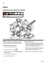
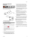
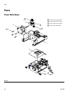

Repair
334135B 43
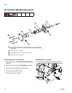
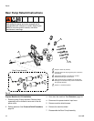
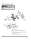
7. Use an open-end wrench to remove all hex nuts
connecting the piston rod to the drive block.
8. Remove the four screws that attach the cylinder rod
end block to the frame. Access the screws through
the four holes in the blind end block using a long
allen wrench.
9. Partially remove the air cylinder by pulling on the
cylinder from the back of the machine until the air
lines at the elbow fittings can be seen.
10. With the cylinder partially removed, disconnect the
airlines at the air cylinder elbow fittings.
11. Finish removing the air cylinder.
12. On a bench, disassemble the air cylinder by remov-
ing the four long screws that connect the two cylin-
der blocks.
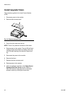
Clean and Inspect the Parts
13. Inspect the cylinder tube and piston for scratches.
Replace if necessary.
14. Using a clean, dry cloth, remove any grease from
the inside of the tube, the outside of the piston, and
the cylinder rod.
15. Remove the two cylinder block o-rings from the
blocks and replace.
16. Remove the piston o-ring and replace.
17. Remove the cylinder rod from the rod end block.
18. Remove the rod o-ring from the rod end block and
replace.
19. Liberally apply high temperature lubricant grease
(part 115982) to the inside of the tube, the outside
of the piston, all the o-rings, and the cylinder rod.
Re-Assemble the Air Cylinder
20. Reinstall the four long screws that attach the two
drive blocks by finger-tightening them. Then torque
the bolts to 350 in-lb (39.5 N•m) in a crisscross pat-
tern.
21. Insert the cylinder rod through the hole in the rod
end cylinder block and base frame.
22. Reinstall the four screws that attach the cylinder rod
end block to the frame.
23. Reinstall the hex nuts to the cylinder rod and torque
to 100 ft-lb (135 N•m).
24. Install the three screws that attach the solenoid
valves to the blind end block. Torque to 41 in-lb
(4.6 N•m).
25. Reinstall the control bracket.
26. Reconnect the air line.
Prepare Machine for Operation
27. Reattach the incoming power bracket by reinstalling
the four attachment screws.
28. Reconnect air input hose.
29. Operate the machine and ensure there are no air
leaks found.
30. Install the machine shield.
31. Install machine shield screws.
32. Calibrate the machine.
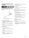
NOTICE
In the following step, the long screws must be tight-
ened in a crisscross pattern. Failure to do so may
result in air cylinder damage.
1
2
3
4