


Repair
334135B 47
Check Valve Rebuild Kit
Installation
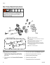
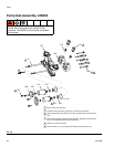
NOTE: See Pump Sub-Assembly, 24S053, page 50 for
pump sub-assembly part references.
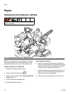
Prepare Machine for Kit Installation
1. Relieve pressure. See Pressure Relief Procedure,
page 33.
2. To prevent machine movement, press the Machine
Disable Mode key ( ).
3. Place a waste container below the dispense valve to
catch any dispensed material.
4. Push the drive block forward until pistons are fully
extended.
5. Move the waste container to below the check valve.
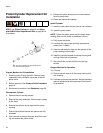
6. Disconnect the male hose fitting from the check
valve housing by loosening the hose from the hous-
ing. See Pump Sub-Assembly, 24S053, page 50.
7. Remove the check valve housing from the pump
endcap by loosening the housing with a wrench.
8. Remove the existing check valve from the housing
by inserting a screwdriver or dowel rod into the
female threaded end of the check valve housing.
9. Place the new check valve ball guide (114.3) on a
bench with the open end up. Install the check valve
spring (114.2) into the guide.
10. Install the check valve ball (114.1) on top of the
spring (114.2).
11. Place the seat (114.4) on top of the check valve
ball (114.1) with the outside chamfered side of the
seat facing away from the check valve ball.
12. Hold both ends of the assembled check valve
assembly and install the check valve into the
unthreaded end of the check valve housing with the
ball end facing out.
13. Apply pressure to the valve to snugly fit the assem-
bled check valve into the check valve housing. Fit
the check valve seat (114.4) into the valve guide.
NOTE: Verify when the assembled check valve and
housing are turned up-side down that the contents of
the check valve stay in place.
14. Use a wrench to insert the new valve and valve
housing into the pump end cap.
15. Install the material male hose fitting into the check
valve housing using a wrench.
16. Before operating the machine, activate a few shots
to purge any air present in the material hose lines.
17. Calibrate the machine if necessary. Perform Setup,
page 26.
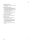
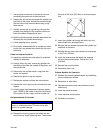
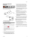
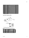
FIG. 13: Check Valve Rebuild Kit
The side of the seat with an outside diameter chamfer
must point away from the ball.
1
114.4
114.1
114.2
114.3
Chamfer
1