


Installation
309298J 9
Installation
Install the System
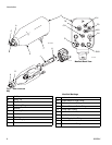
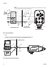
FIG. 2. shows a typical electrostatic air-assisted spray
system, and F
IG. 3. shows possible system options. It is
not an actual system design. For assistance in design-
ing a system to suit your particular needs, contact your
Graco distributor.
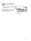
Warning Signs
Mount warning signs in the spray area where they can
easily be seen and read by all operators. An English
Warning Sign is provided with the gun.
Ventilate the Spray Booth
Electrically interlock the gun turbine air supply with the
ventilators to prevent gun operation without ventilating
fans operating. Check and follow all National, State, and
Local codes regarding air exhaust velocity require-
ments.
High velocity air exhaust will decrease the operating effi-
ciency of the electrostatic system. The minimum allow-
able air exhaust velocity is 60 ft/minute (19 linear
meters/minute).
Key to F
IG. 2. and FIG. 3.
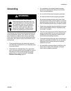
WARNING
Fire, Explosion, and Electric Shock Hazard
Installing and servicing this equipment
requires access to parts which may cause
electric shock or other serious injury if work
is not performed properly.
•Do not install or service this equipment
unless you are trained and qualified.
•Be sure your installation complies with
National, State and Local codes for the
installation of electrical apparatus in a Class
I, Div. I, Group D or a Group II,
Category 2G Hazardous Location.
• Comply with all applicable local, state, and
national fire, electrical, and other safety regula-
tions.
WARNING
Flammable or Toxic Vapor Hazard
Provide fresh air ventilation to avoid the buildup of
flammable or toxic vapors when spraying, flushing, or
cleaning the gun. Do not operate the gun unless ven-
tilation fans are operating.
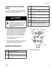
A Air Hose Ground Wire
B Graco Grounded Turbine Air Hose (TA)
C Atomizing Air Hose, 3/8 in. (10 mm) OD (A2)
E Cylinder Air Hose, 5/32 in. (4 mm) OD (CYL)
F Fluid Hose, 1/4-18 npsm gun fluid inlet (P1)
G To Fluid Supply
H Auto PRO Xs Air-Assisted Spray Gun
J Mounting Bracket for 1/2 in. (13 mm) rod
K Solenoid Valve, requires quick exhaust port
L Bleed-Type Master Air Valve
M Air Pressure Regulator
N True Earth Ground
P 24 Volt Power Supply
Q 4-20 microampere Outputs
R Full Feature ES Display Module
S kV Only ES Display Module (battery operated)
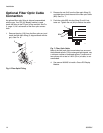
T Fiber Optic Y Cable
U Bulkhead
V Fiber Optic Cable
W Main Air Line
X
kV Switch Air Hose, 5/32 in. (4 mm) OD (optional; plug KV1
fitting if not used)
Y
kV Switch Air Hose, 5/32 in. (4 mm) OD (optional; plug KV2
fitting if not used)