


-26-
G0459 12" Drum Sander
Tools Needed: Qty
Hex Wrench 6mm ..............................................
1
Wrench 12mm ...................................................
1
Straightedge ...................................................... 1
Ruler .................................................................. 1
Phillips Head Screwdriver #2 ............................
1
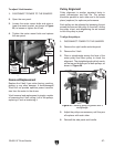
Tension
A new V-belt often stretches and loosens up dur-
ing the first 16 hours of use. After this period, it
should be inspected and re-tensioned if neces
-
sary.
Proper tension is important for optimum power
transmission. However, too much tension may
cause premature bearing failure.
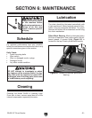
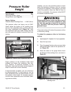
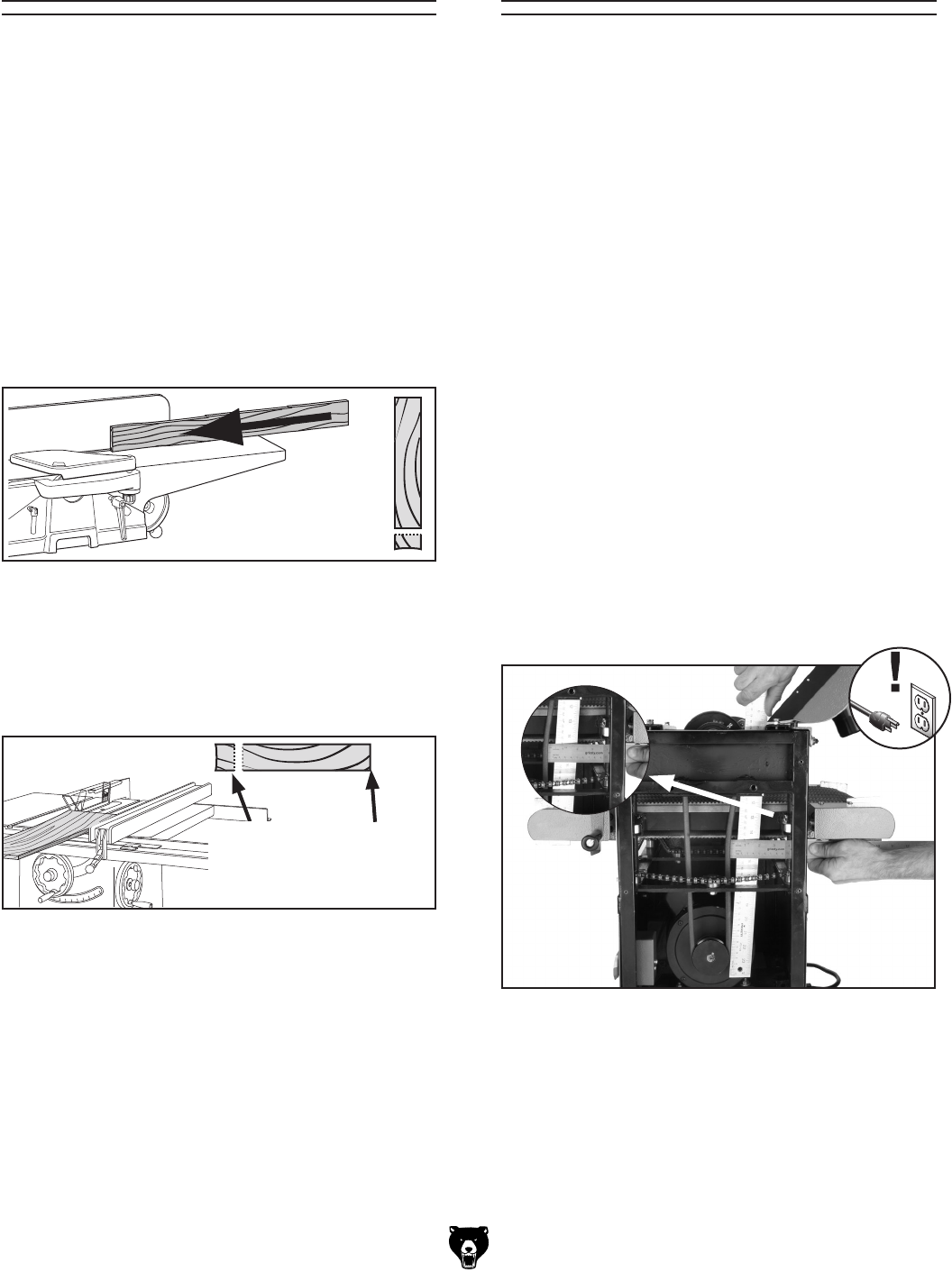
To test V-belt tension:
1. Remove the right handle and side panel.
2. Using a straightedge and ruler (Figure 24),
push on the middle of the V-belt.
The correct
V-belt tension is achieved when the V-belt
can be deflected
1
⁄2"–
3
⁄4" with moderate pres-
sure.
V-Belt Service
Figure 24. Checking V-belt tension with a
straightedge and a ruler
.
Tools Needed: Qty
6' Long 2x4 ........................................................
1
Miter Saw (or Circular Saw) ..............................
1
Jointer ................................................................ 1
Table Saw .........................................................
1
The gauge blocks described here will be required
to complete most of the service procedures in this
section.
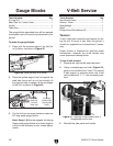
To make the gauge blocks:
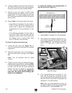
1. Edge joint the concave edge of the 2x4 flat
on a jointer, as shown in
Figure 22.
Gauge Blocks
Previously
Jointed Edge
Held Against
Fence
Figure 22. Edge jointing on a jointer.
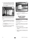
2. Place the jointed edge of the 2x4 against the
table saw fence and rip cut just enough off
the opposite side to square up the two edges
of the 2x4, as shown in
Figure 23.
Opposite
Edge Rip
Cut with
Table Saw
3. Cut the 2x4 into two even pieces to make two
36" long wood gauge blocks.
Note: Steps 1 & 2 can be skipped, but having
these wood gauge blocks at an even height is
critical to the accuracy of your overall adjust
-
ments.
Figure 23. Rip cutting on a table saw.
3. Reinstall the side panel and handle.