


G0459 12" Drum Sander
-29-
Tools Needed: Qty
Hex Wrench 4mm ..............................................
1
Wrench 19mm ...................................................
1
Wrench 10mm ...................................................
1
Socket 14mm ....................................................
1
Measuring Tape ................................................
1
Gauge Blocks (see
Page 26) ............................ 2
Feeler Gauge Set ..............................................
1
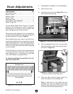
For the Model G0459 Drum Sander to function
properly, the sanding drum must be aligned in
two directions: (1) parallel to the conveyor belt
and (2) perpendicular to feed direction.
The drums can be adjusted in fine increments at
the pillow block bearings and in larger increments
by using the table lift screws (Page 33).
While adjusting the drum, keep in mind that hav
-
ing the drum parallel to the conveyor belt is critical
to the sanding operation. Care should be taken to
make the tolerances as close as possible (within
0.002" from one side to the other) when adjusting
the drum height.
The tolerances for having the drum perpendicular
to the feed direction are much more forgiving,
even allowing up to
1
⁄8" difference from one side
to the other before causing problems.
To align the sanding drum parallel to the con
-
veyor belt (Figure
28):
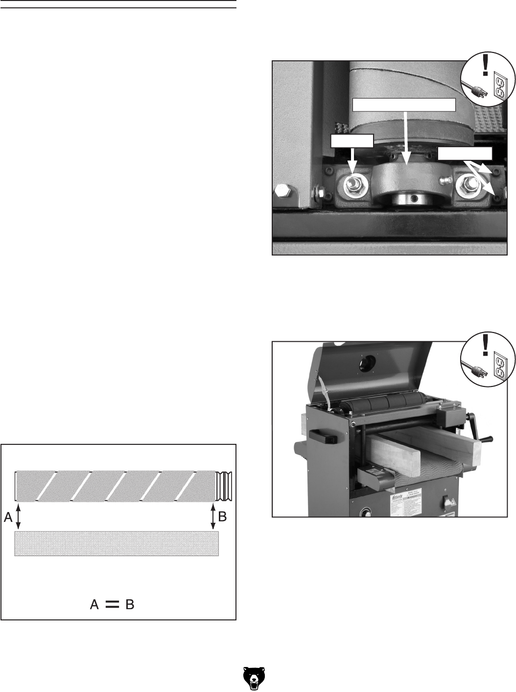
Drum Adjustments
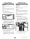
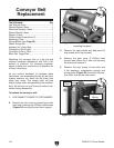
Figure 28. Drum parallel to conveyor belt.
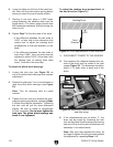
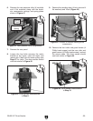
Locknut
Figure 29. Pillow block bearing adjustments.
Pillow Block Bearing
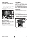
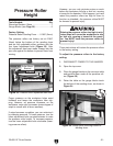
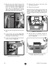
4. Place the gauge blocks on the conveyor table
and position them under the pressure rollers,
as shown in
Figure 30.
Figure 30. Gauge blocks positioned under
pressure rollers and sanding drum.
5. Raise the table until the gauge blocks just
touch the bottom of the sanding drum.
Note: A good way to know when they are
touching is to rock the sanding drum back
and forth while raising the table until you hear
or feel contact with the gauge blocks.
1. DISCONNECT POWER TO THE SANDER!
2. Open the top cover.
3. Loosen the lock nuts (see Figure 29) on the
drum pillow block bearing.
Setscrews