


G0459 12" Drum Sander
-37-
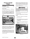
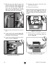
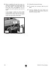
Figure 50. Conveyor belt removed from table.
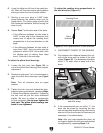
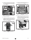
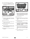
Figure 49. Rear left roller bracket loosened.
20. Remove the conveyor motor chain.
21. Remove the conveyor motor (2 cap screws)
and the rear roller bracket (2 cap screws)
shown in
Figure 49.
22. Remove the rear roller.
23. Remove the front left roller bracket (2 cap
screws) and the front roller.
24. Remove the front right and rear roller brack-
ets (4 cap screws).
25. Place the right side of the conveyor on a flat
surface, then unthread and remove the front
and rear table lift screws.
26. Remove the belt. The table should look like
Figure 50.
27. Measure the distance between the front right
table lift screw sprocket and the mounting
bracket. If necessary, rotate the rear shaft so
the sprocket-bracket distance is the same as
the front right table lift screw.
28. Install the new belt.
29. Reinstall the front left and rear left table lift
screws to match the front right lift screw
height.
30. Reassemble the drum sander by reversing
the disassembly steps.
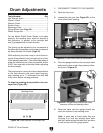
31. After reassembly, adjust the drums and pres-
sure rollers to their proper settings. See
Drum
Adjustments on Page 29 and Pressure
Roller Height on
Page 31.
32. After you have reinstalled the conveyor table,
make sure the four lower pressure roller
adjustment bolts are threaded the same dis
-
tance into the roller mount brackets (
Figure
33).
33. After reinstalling the top cover and brace,
tighten the mounting bolts.
18. Lay the conveyor table on a flat surface.
19. Loosen the rear left (Figure 49) roller bracket
(2 cap screws) enough so the conveyor motor
chain is slack.
Front
Right
Sprocket
Mounting
Bracket
Rear Left
Roller
Bracket
Conveyor
Motor Chain
Conveyor
Motor
Rear
Lift Screw