


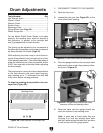
G0459 12" Drum Sander
-33-
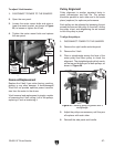
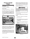
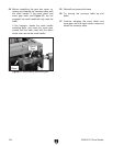
5. Loosen the chain by loosening the hex nut on
the bottom of the idler roller sprocket shown
in Figure 38.
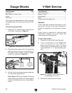
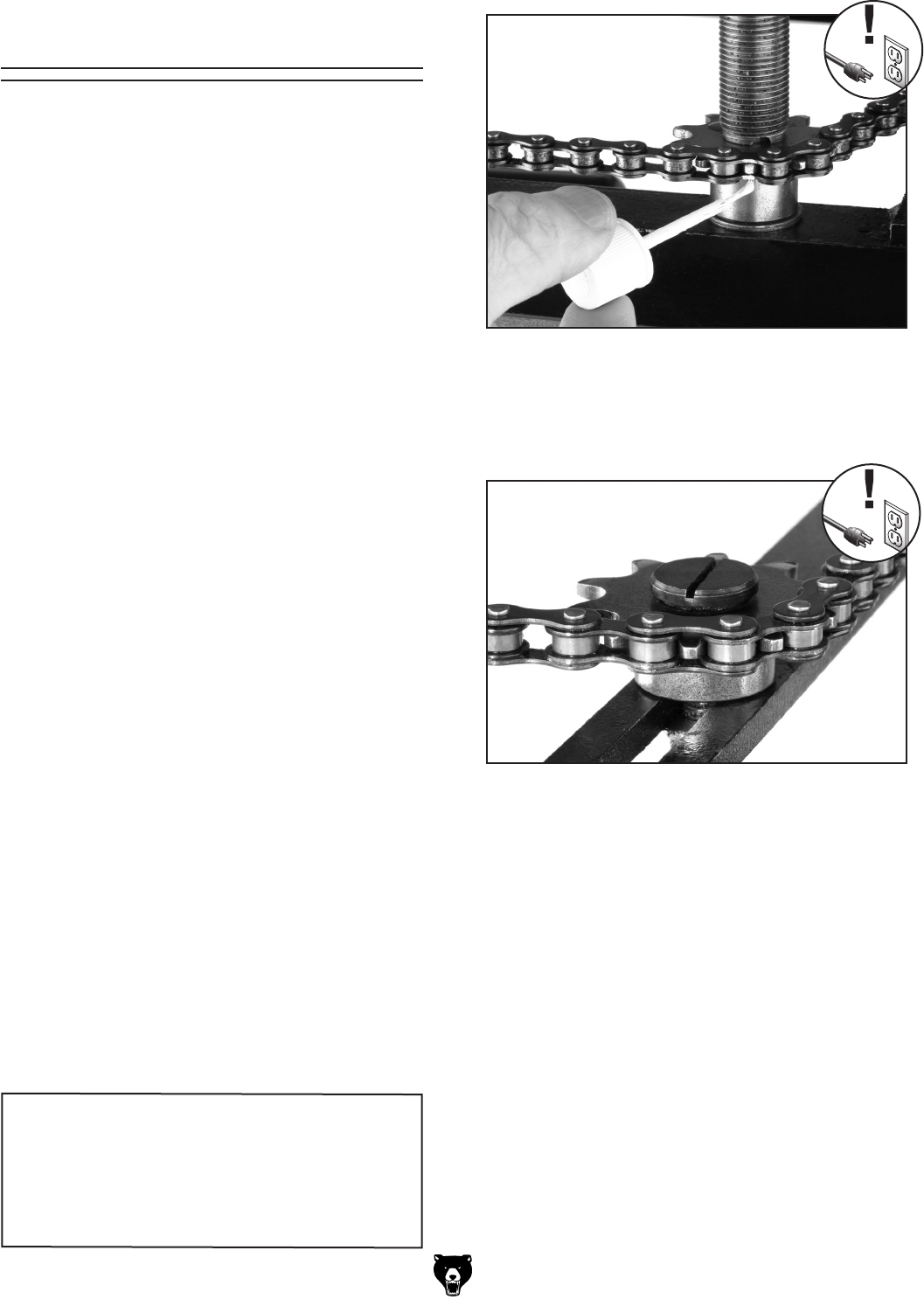
Figure 37. Marking sprocket tooth and chain.
Tools Needed: Qty
Hex Wrench 6mm ..............................................
1
Wrench/Socket 12mm .......................................
1
Chalk, Correction Fluid, or Paint .......................
1
Phillips Head Screwdriver #2 ............................
1
Flat Head Screwdriver .......................................
1
The table lift screws are connected by a chain
and driven by the crank handle. (When the chain
is removed from a sprocket on one of the lift
screws, that lift screw can adjust that portion of
the table up/down independently to assist in set
-
ting the table parallel to the drum.)
Adjusting the table lift screws will only be neces
-
sary if you need to adjust the drum height more
than allowed at the pillow block bearing adjust
-
ments, or if you have removed the table or chain
(see Page 37
) during a service procedure and
you need to reset the drum parallel to the table
.
Each complete tooth rotation on the sprocket
represents 0.007" or .18mm of table elevation
movement. For example, if the rear of the table
was
0.007" low, rotate both rear table lift screws
to the next sprocket tooth in the same chain posi
-
tion. You can easily rotate the sprockets from
the top of the table lift screws with a flat head
screwdriver.
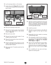
To adjust the table lift screws:
1. DISCONNECT POWER TO THE SANDER!
2. Open the right side and front panels.
3. Raise the table up to at least the 1" mark on
the height scale.
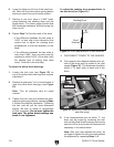
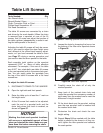
4. At the lift screw that needs to be adjusted,
mark the end of a sprocket tooth and the
chain hole where that tooth is meshed, as
shown in
Figure 37.
Table Lift Screws
6. Carefully move the chain off of only the
marked sprocket.
7. Keep track of the marked chain hole and
rotate the sprocket the necessary number of
teeth away from the marked one to meet the
difference in height needed.
8. Fit the chain back over the sprocket, making
sure the new sprocket tooth is inserted into
the marked chain hole.
9. Re-tension the chain and check the new
height setting.
10. Repeat Steps 5–9 as needed until the table
height is parallel to the drums in all four cor
-
ners, tighten the idler sprocket and calibrate
the scale pointer.
Figure 38. Idler roller sprocket.
NOTICE
Marking the chain and sprocket locations
will save you a substantial amount of time
when you reinstall the chain. Make sure you
have done this before removing the chain.