


-34-
G0459 12" Drum Sander
Tools Needed: Qty
Hex Wrench 6mm ..............................................
1
Wrench/Socket 19mm .......................................
1
Wrenches/Sockets 14mm .................................
2
Wrench/Socket 12mm .......................................
1
Wrench 10mm ...................................................
1
Phillips Head Screwdriver #2 ............................
1
Measuring Tape ................................................
1
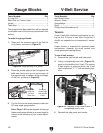
Gauge Blocks (see
Page 26) ............................ 2
Feeler Gauge Set ..............................................
1
Assistant for Lifting Help ...................................
1
Flashlight or Work Light ....................................
1
Correction Fluid or Paint ...................................
1
Black Felt Tipped Pen .......................................
1
Replacing the conveyor belt is a big job and
requires moderate mechanical skill and a fair
amount of patience. For planning purposes,
expect to have your machine out of operation for
at least a few hours.
As you remove hardware to complete these
instructions, we recommend putting all the bolts,
screws, washers, etc. back into the holes from
which they came. This simple habit will take
slightly longer when disassembling the machine,
but it will save you a lot of time and reduce frus
-
tration during reassembly.
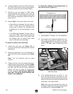
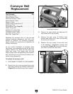
To replace the conveyor belt:
1. DISCONNECT POWER TO THE SANDER!
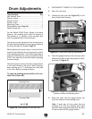
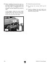
2. Remove the top cover by loosening the hex
bolts and removing the Phillips head screws
(Figure 39) securing the top cover support.
Conveyor Belt
Replacement
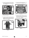
3. Remove the right handle and side panel (2
cap screws and 6 tap screws).
4. Remove the gear cover (2 Phillips head
screws) and loosen the 2 hex nuts securing
the brace and remove it.
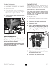
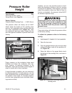
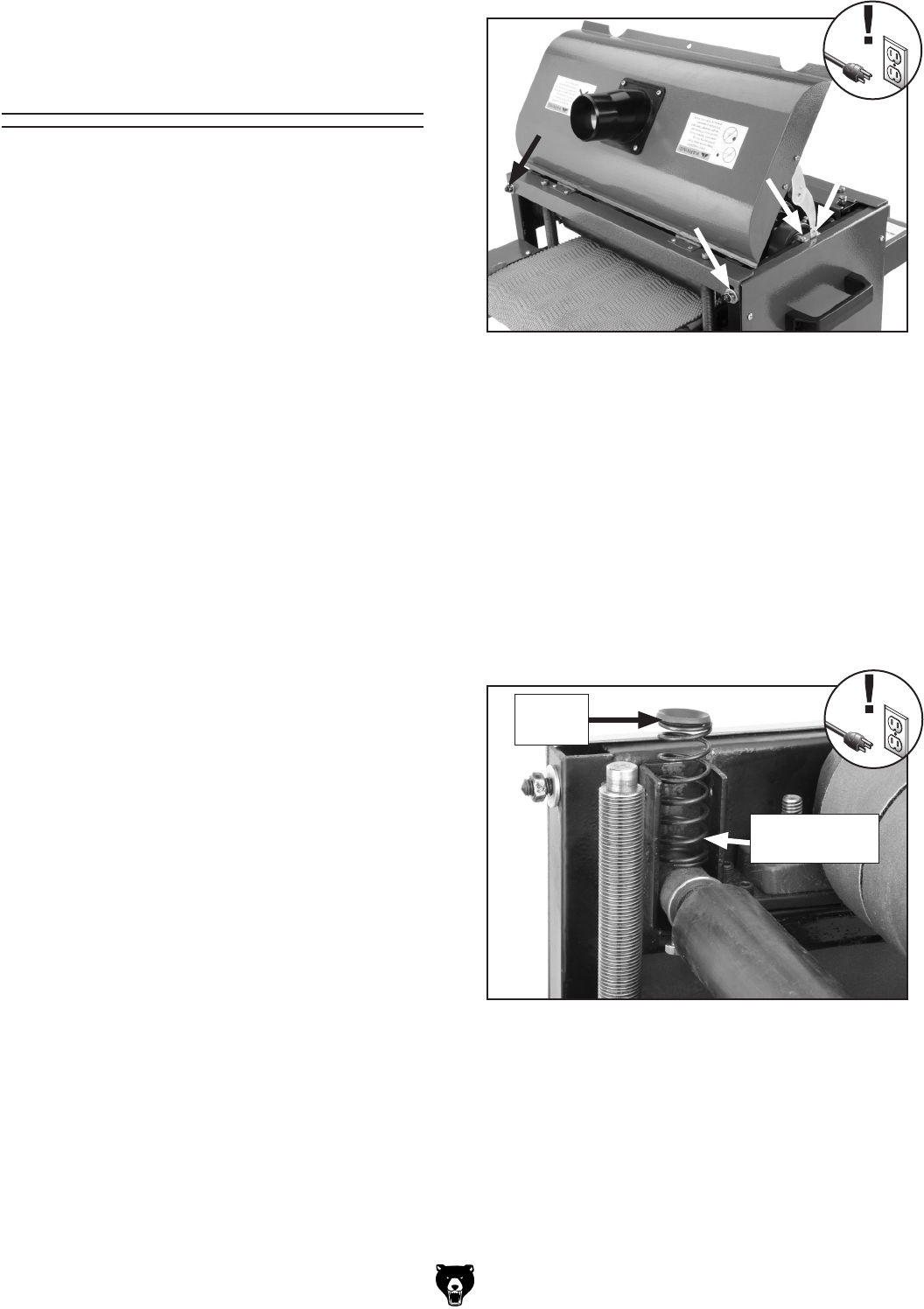
5. Remove the dust scoop (4 hex bolts and
4 flat washers), compression springs and
spring plates (
Figure 40) from the front pres-
sure roller and set the roller aside.
NEW
PHOTO
Figure 39. Locations to remove top cover
mounting hardware.
Figure 40. Front pressure roller components.
Spring
Plate
Compression
Spring