


G1015 Knife Belt Sander/Buffer -10-
SECTION 4: ASSEMBLY
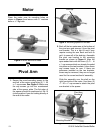
Mounting Base
All die-cut metal parts have a sharp edge
(called “flashing”) on them after they are
formed. This is generally removed at the
factory. Sometimes a bit of flashing might
escape inspection, and the sharp edge may
cause cuts or lacerations when handled.
Please examine the edges of all die-cut
metal parts and file or sand the edge to
remove the flashing before handling them.
Failure to do so could result in injury.
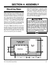
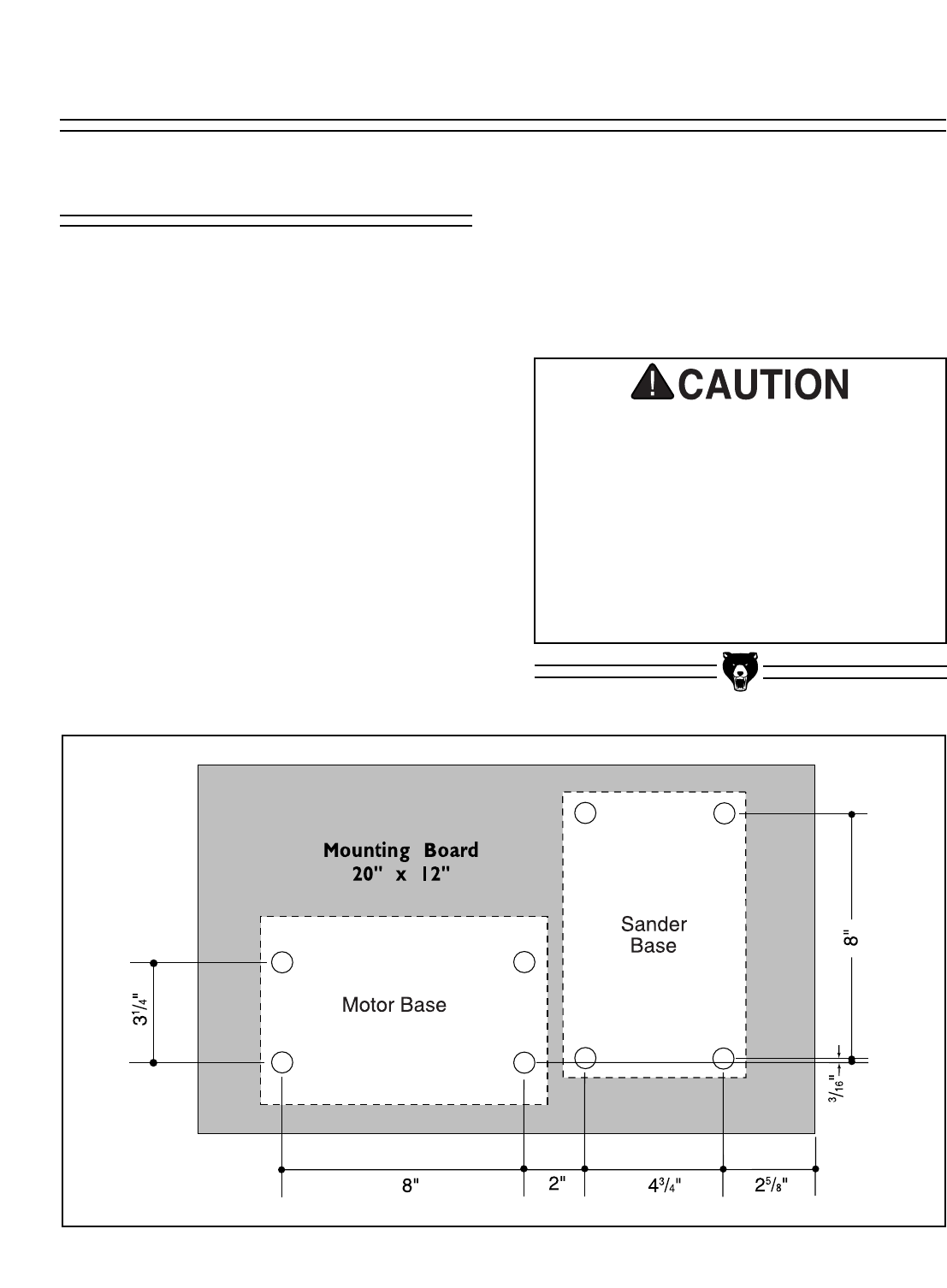
Figure 3. Bolt pattern for base. All dimensions are measured at hole centers.
Before assembly can be completed, the Model
G1015 motor base and belt sander base must
both be mounted to a bench, or a wooden base,
to provide the stability necessary for safe opera-
tion. If you choose to create a wooden base for
more portable operation, we recommend laminat-
ing two 20" x 12" x
3
⁄4" pieces of plywood togeth-
er, or use 1'' thick MDF (medium density fiber-
board). For a wooden base, you may also want to
countersink the underside to accommodate the
hex nut and washers so the base will sit flat.
The layout in Figure 3 provides the recommend-
ed pattern for both motor base and sander base
mounting. Because of variation in the castings,
you may want to drill only the holes for the motor
base, then drill the sander base holes later after
you have mounted the pivot arm assembly.
Holes should be drilled for
5
⁄16" lag bolts (
1
⁄4" pilot
hole) or
5
⁄16" machine bolts (
1
⁄2" diameter will allow
some minor adjustment). Mounting hardware is
not included. If using machine bolts, use a lock
washer secured between a flat washer and the
nut to ensure the bolt will not loosen during oper-
ation. Continue with the mounting procedure as
described in the following pages.