


-15- G1015 Knife Belt Sander/Buffer
SECTION 5: Adjustments
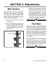
Belt Tension
The Model G1015 features a self-tensioning
mechanism which automatically applies tension
to the sanding belt. If you are using a different
length belt than the one supplied (72'') you will
need to adjust the distance between the two
wheels. To adjust the tensioning:
1. Pull down the tensioning knob and remove
the sanding belt.
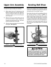
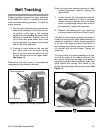
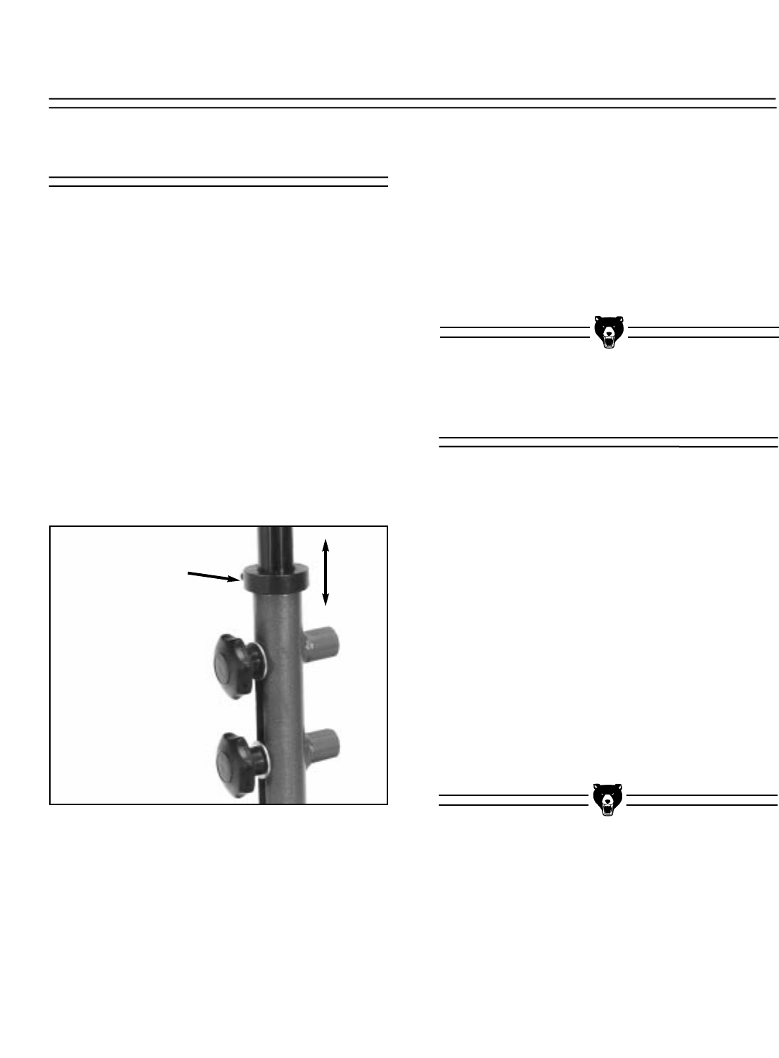
2. Loosen the hand knobs on the pivot arm
and raise or lower the upper assembly to
increase or decrease the distance between
the wheels. See Figure 13. You may need
to loosen the stop collar to allow the neces-
sary movement.
Figure 13. Length adjustment for upper arm.
Stop Collar
3. Replace the sanding belt onto the wheels
and inspect for tension. Be sure the track-
ing adjustment is set so the upper wheel
shaft is almost perpendicular. The belt
should deflect approximately
1
⁄2'' inch when
you press against it. Check it on the back
loop of the belt where it comes up from the
drive wheel to the upper wheel. This way
the deflection will not be affected by the
sanding shoe. Repeat step 2 if needed.
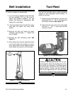
Tool Rest
The tool rest should be adjusted so it is posi-
tioned in front of the sanding belt shoe’s graphite
surface. The clearance between the tool rest and
the belt should be no more than
1
⁄8'' to ensure that
nothing can become trapped between the belt
and the rest. The angle of the rest relative to the
belt surface can be adjusted by loosening the cap
screw, adjusting the rest angle and re-tightening
the cap screw.
The height of the tool rest can also be adjusted
by removing the two (2)
5
⁄16" - 18 x 1
1
⁄4" cap screws
holding the two halves of the tool rest bracket
together. Selection of different hole combinations
results in varying lengths. The tool rest should be
set high enough so that it is located over the
graphite pad portion of the sanding shoe.