


-11-
Motor
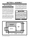
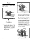
Place the motor over its mounting holes as
shown in Figure 4 and secure with
5
⁄16" machine
bolts or
5
⁄16" lag bolts.
Figure 4. Motor secured to base.
Pivot Arm
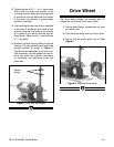
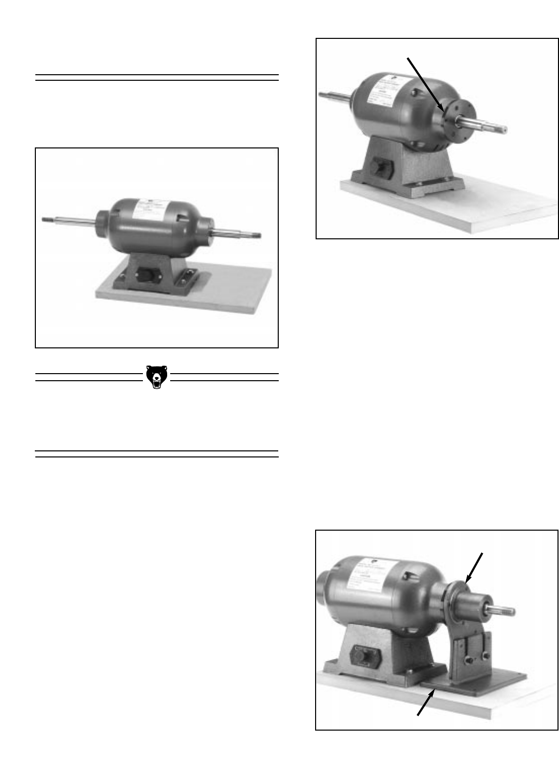
1. Secure the round mounting spacer to the
end bell of the motor using three (3)
1
⁄4 - 20
x
1
⁄2'' cap screws. See Figure 5. Make sure
the cap screws go into the countersunk
side of the spacer plate. The flat edge of
the spacer should be positioned at the 10
o’clock position if you are looking directly at
the end of the motor.
Figure 5. Mounting spacer to end bell.
Flat Edge
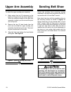
Figure 6. Bracket assembly attachment.
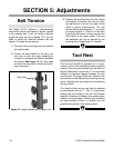
2. Back off the two setscrews at the bottom of
the pivot arm and remove it from the pivot
arm bracket. This is a tight fit and it may
require moving the arm back and forth to
get it to come off of the bushing. Assemble
the pivot arm bracket to the mounting
bracket as shown in Figure 6. Align the
open ended slots with the three (3)
5
⁄16" - 18
x 1" cap screws which are already threaded
into place on the two brackets. Leave these
cap screws loose for now. If there are
setscrews installed on the two brackets,
these may be removed, they are no longer
used for the current method of assembly.
Slide this assembly over the shaft on the
right hand side of the motor. Use three (3)
1
⁄4'' - 20 x
1
⁄2'' cap screws to attach the pivot
arm bracket to the spacer.
Pivot Arm
Bracket
Mounting Bracket
G1015 Knife Belt Sander/Buffer