


-26-
G9729 Combination Lathe/Mill
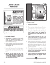
Tool Post
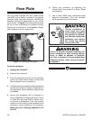
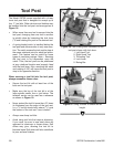
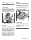
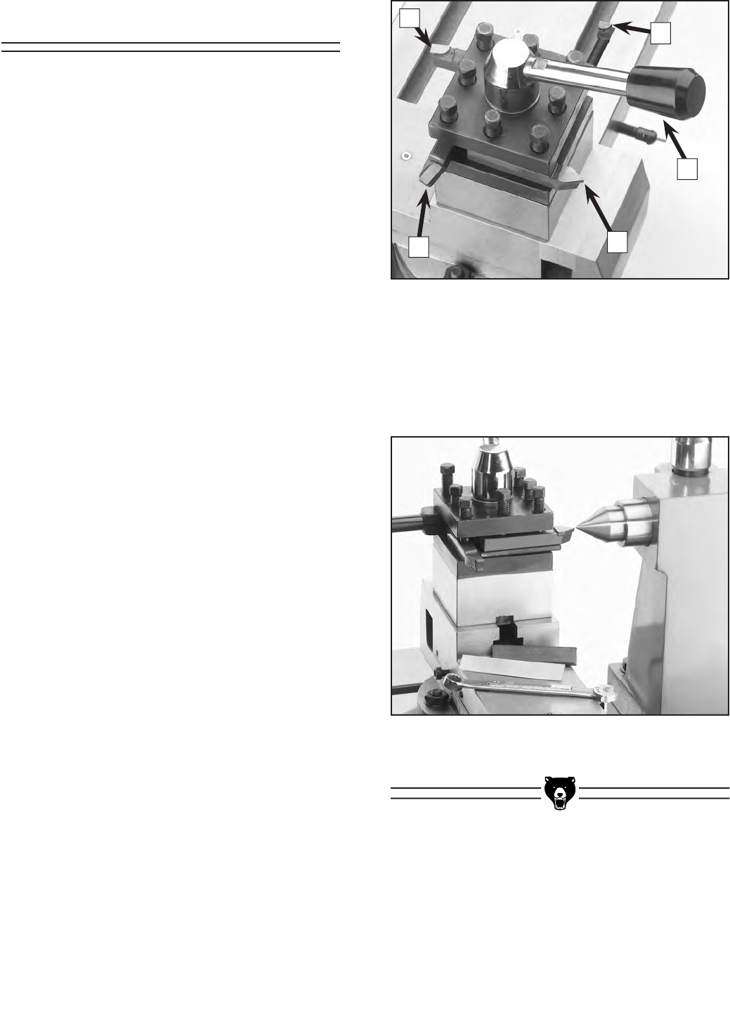
Figure 18. Four cutting tools mounted into the
tool post shown with lock lever.
1. Left Hand Tool
2. Right Hand Tool
3. Threading Tool
4. Lock Lever
5. Boring Bar
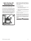
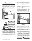
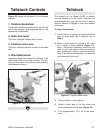
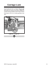
Figure 19. Using a center to check tool bit
height.
The Model G9729 comes supplied with a 4-way
turret tool post that is designed to accept up to
four
1
⁄2" tool bits. Other devices and holders may
be installed into the tool post and arranged as in
Figure 18.
• When more than one tool is secured into the
tool
post, changing from one tool to another
is quickly done by loosening the lock lever
(
#
4) and rotating the post to the desired tool.
• A spring-loaded catch is installed below the
tool post and allows motion in only one direc-
tion.
The catch causes the tool post to stop at
the same rotational point for each tool place-
ment.
This feature can be useful for some
types of machining setups. Note— Securing
the
tool post is not dependent upon the
catch. Thus, the tool post can be positioned
at any rotational location and properly fixed
with the lock lever. Also, removing the catch
and rotating it 180˚ will cause the tool post to
stop in the opposite direction.
When securing a tool bit into the tool post,
always remember these rules:
• Secure the tool bit with at least two of the
bolts on the tool post.
• Make sure the top of the tool bit is at the
lathe spindle center line or just below. The
tailstock center can be used as a reference
as shown in Figure 19.
•
Never extend the tool bit more than 2
1
⁄2 times
its thickness from the edge of the tool rest.
I.e. a
3
⁄8" tool bit should only extend
15
⁄16
" past
the bottom of the tool rest. Less is better!
• Always use sharp tool bits.
• Avoid using tool bits that require shimming.
If you must, be sure to use steel shims as
opposed to aluminum or brass shims. Soft
shims may give, allowing the tool bit to
become loose! Soft shims will also contribute
to poor surface finishes.
1
2
3
4
5