


-44-
G9729 Combination Lathe/Mill
SECTION 5: MILL OPERATIONS
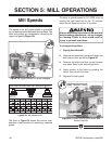
Mill Speeds
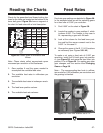
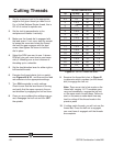
Figure 55. Mill speed chart.
Figure 54. Upper pulleys for speed changes.
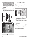
The speed of the drill press spindle is controlled
by two belts mounted between three pulleys. The
belts
and pulleys are accessed by removing the
upper belt guard (Figure 54).
To
select a spindle speed of 310 RPM, start by
moving the right hand belt to the “D” position.
Move the left hand belt to the “A” position.
The chart in Figure 55 shows the various com-
binations
of belt positions for achieving a desired
speed.
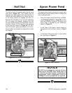
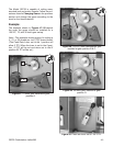
To
change belt position:
1. Unplug the lathe/mill!
2. Remove
the upper belt guard and loosen the
belt tension lever as shown Figure 56.
3. Remove the belts from their current location
and
place them in the desired positions.
4. Apply tension to the belts by pivoting the
motor.
Secure with the lever.
5. Replace the belt guard.
THE DRILLING-MILLING UNIT SPEEDS ( /min)
A
A B A C A D B A
E E
D E C E D B
B C
B D C D C D
C D
A C B B A A
B
C
D
E
MOTOR
MIDDLE
SPINDLE
120 200 310 350 400 450 530 600
660 900 1380 1450 1670 2140 2350 3000
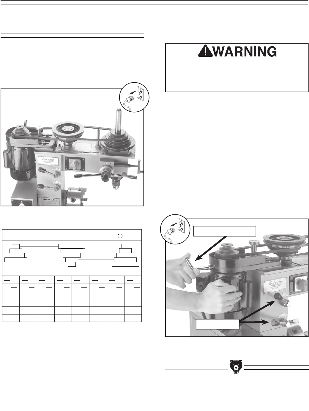
Figure 56. Loosen stud to pivot motor and
tension the belt.
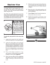
Always disconnect the power to the machine
before making adjustments, set-up changes
or cleaning. Failure to do so could result in
injury to yourself and others.
Belt Tension Lever
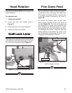
Head Locks